Printing apparatus and printing method

a printing apparatus and printing method technology, applied in the field of apparatus and printing method for on-demand offset printing, can solve the problems of not providing sufficient color uniformity, electrophotographic printers cannot support printing on thin paper such as newsprint, and a lot of time and cost, and achieve the effect of reducing printing costs

Inactive Publication Date: 2011-05-26
CANON KK
View PDF2 Cites 3 Cited by
  • Summary
  • Abstract
  • Description
  • Claims
  • Application Information

AI Technical Summary

Benefits of technology

[0013]The present invention is proposed in view of the foregoing circumstances, and provides an offset printing apparatus in which ink-repellent particles are adhered to a plate forming member to form a plate, and in which the ink-repellent particles are reused while preventing the ink-repellent particles from being deformed, damaged, or lost. The use of such an offset printing apparatus can prevent waste of the ink-repellent particles for the plate forming member, and reduce the printing cost.

Problems solved by technology

While modern electrophotographic printers provide a drastically improved image quality, they may not provide sufficient color uniformity (cause significant color differences) in printed materials, the entire surface of which is colored in a single color, or may curl printed materials.
In addition, electrophotographic printers do not support printing on thin paper such as newsprint.
However, the planographic offset printing requires much time and cost for plate making, and therefore incurs a high cost in the case where the number of prints to be output is small.
Thus, the planographic offset printing is not widely used for purposes other than printing a large number of prints.
In addition, a plate material once fabricated for offset printing cannot be diverted to other printing processes and must be disposed of after the intended printing.

Method used


Image

  • Printing apparatus and printing method
  • Printing apparatus and printing method
  • Printing apparatus and printing method

Examples


first embodiment

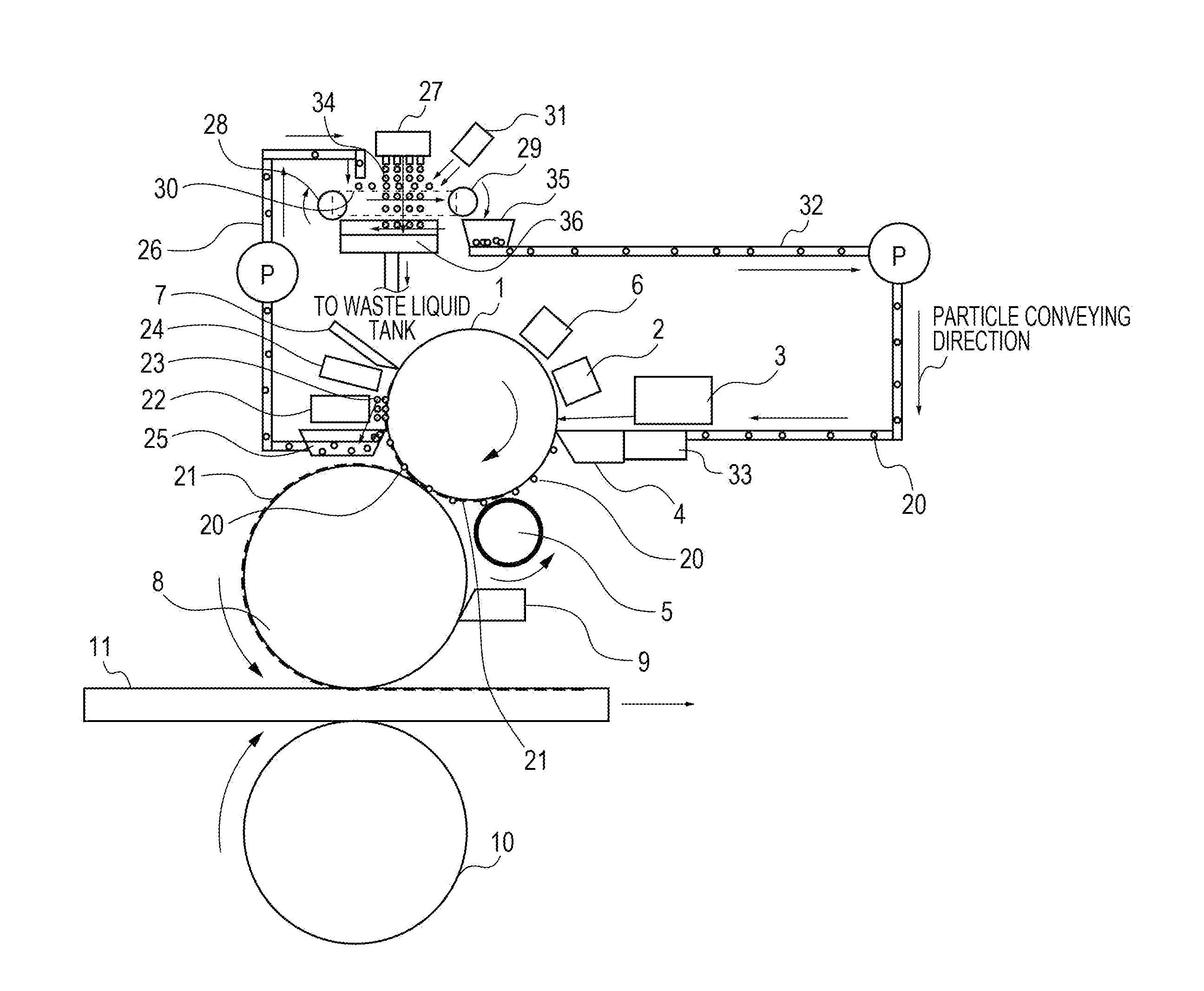
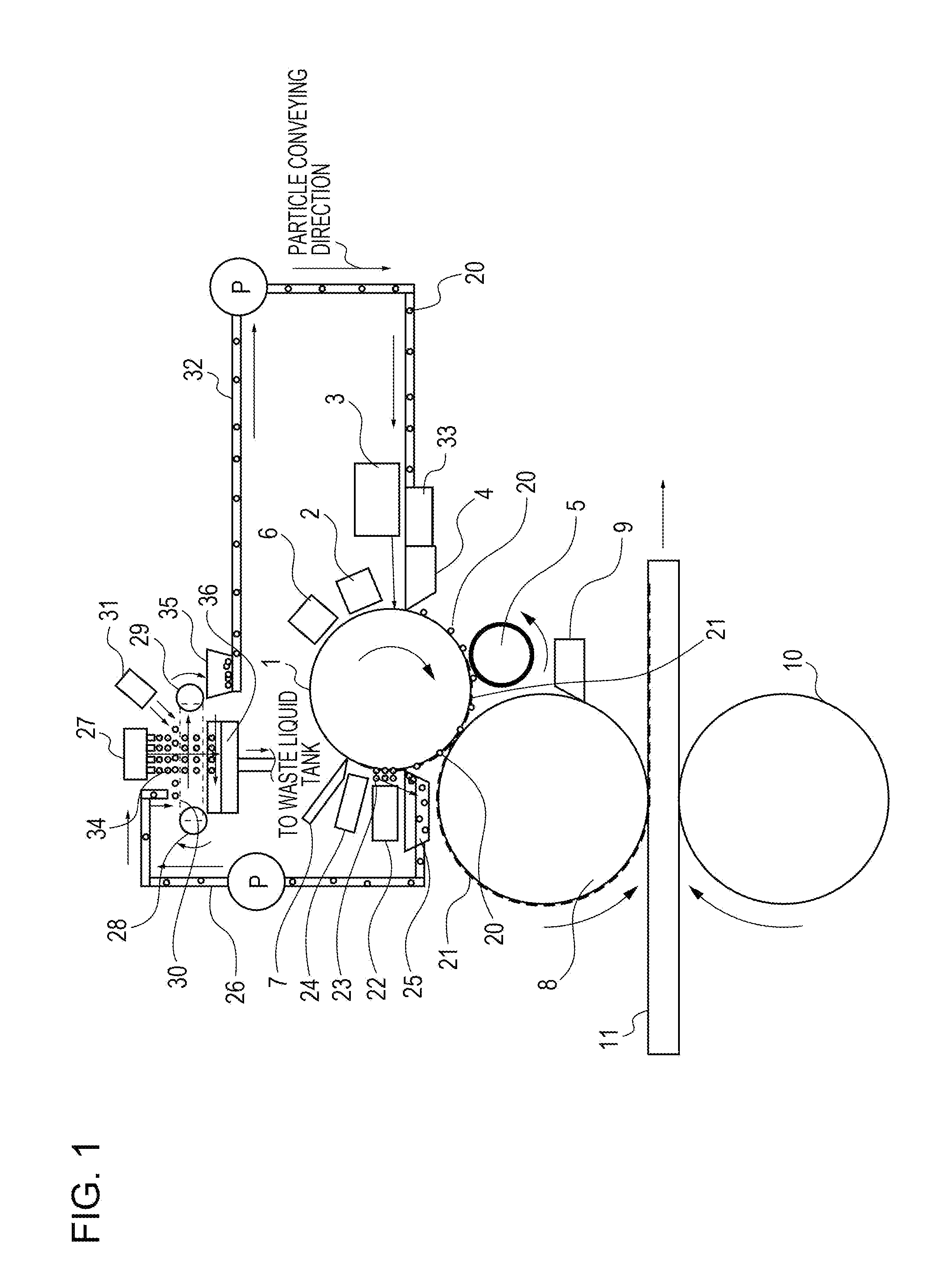
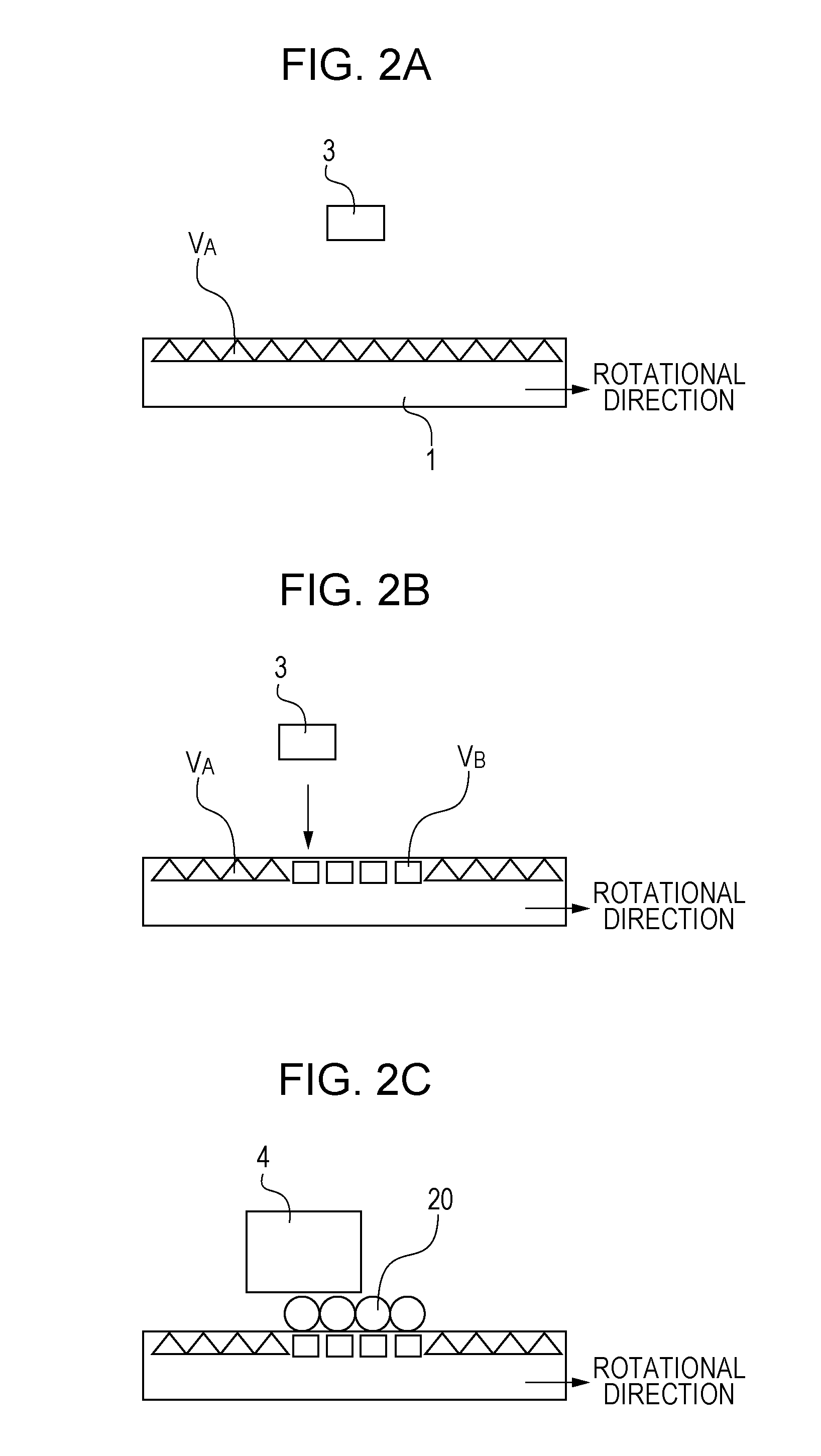
[0026]A first embodiment of the present invention will be described with reference to FIGS. 1, 2A to 2C, and 3A and 3B. As shown in FIG. 1, a printing apparatus according to the embodiment includes a photosensitive drum 1 serving as a plate forming member that forms a rewritable plate and made of an amorphous silicon photosensitive member (a-Si). A charger 2, an exposure unit 3, a developing unit 4, an ink roller 5, a charge eliminating unit 6, and a cleaner blade 7 are disposed around the photosensitive drum 1. The exposure unit 3 is formed as a latent image forming unit that writes a latent image onto a surface of the photosensitive drum 1 serving as a plate forming member. The developing unit 4 is formed as a projection forming unit that selectively adheres ink-repellent particles 20 to a portion of the surface of the photosensitive drum 1 serving as a plate forming member where the latent image is formed in order to form a projection. The ink roller 5 is formed as a recording ma...

second embodiment

[0058]In the first embodiment, the viscosity modifying agent 23 is applied from the viscosity modifying agent application section 22 to reduce the viscosity of the ink 21 adhering to the photosensitive drum 1. In addition, the ink 21 and the viscosity modifying agent 23 adhering to the photosensitive drum 1 are heated by the ink heating section 24 to reduce the viscosity of the ink 21 and the viscosity modifying agent 23.

[0059]In a second embodiment, meanwhile, a cleaner blade heater 39, a particle washing section heater 37, and a blower heater 38 are provided to mainly reduce the viscosity of the ink 21.

[0060]In the description below, components that are substantially identical to those of the first embodiment described with reference to FIGS. 1, 2A to 2C, and 3A and 3B are not described. A second embodiment of the present invention will be described with reference to FIG. 4.

[0061]In FIG. 4, the cleaner blade 7 is provided with the cleaner blade heater 39, which heats the cleaner b...


PUM


Abstract

A printing apparatus includes a plate forming member that forms a rewritable plate, a latent image forming unit, a projection forming unit configured to selectively adhere ink-repellent particles to a portion of a surface of the plate forming member where a latent image is formed in order to form a projection, a recording material supply unit, an intermediate transfer member for transfer of a recording material, a pressing unit configured to press the recording material on a surface of the intermediate transfer member during transfer of the recording material to a recording medium, and a conveying unit configured to convey the medium. The printing apparatus further includes a particle storage unit configured to store the particles, and a particle washing unit configured to wash at least part of the removed particles. At least part of the removed and washed particles is filled into the particle storage unit.

Description

BACKGROUND OF THE INVENTION[0001]1. Field of the Invention[0002]The present invention relates to an apparatus and a method for on-demand offset printing.[0003]2. Description of the Related Art[0004]Various types of so-called electrophotographic printers such as laser beam printers and LED (light emitting diode) printers have been proposed in the related art, and are widely used for the purpose of on-demand printing. Meanwhile, planographic offset printing has been used since a long time ago for the purpose of producing a large number (for example, 1000 or more) of printed materials of the same content by using a plate.[0005]While modern electrophotographic printers provide a drastically improved image quality, they may not provide sufficient color uniformity (cause significant color differences) in printed materials, the entire surface of which is colored in a single color, or may curl printed materials. In addition, electrophotographic printers do not support printing on thin paper...

Claims


Application Information

Patent Timeline
Patent Type & Authority Applications(United States)
IPC IPC(8): B41F7/00
CPCG03G15/104G03G13/28
Inventor ARAKI, YOSHIMASA
Owner CANON KK
Why Eureka
Try Eureka