Nuclear Grade Air Accumulation, Indication and Venting Device

a technology of nuclear grade air and accumulation, applied in the direction of nuclear elements, functional valve types, greenhouse gas reduction, etc., can solve the problems of failure of those systems, unsatisfactory solutions, and failure of those systems

Active Publication Date: 2011-05-26
NUCCORP
View PDF8 Cites 15 Cited by
  • Summary
  • Abstract
  • Description
  • Claims
  • Application Information

AI Technical Summary

Problems solved by technology

Air and gas accumulation in these fluid systems could result in failure of those systems and in their failure in turn to prevent fuel damage.
These solutions are unsatisfactory because they require radiation exposure of workers when there may be no need for testing or venting.
Also, UT probes, in general, cannot remain connected to the piping system in question due the temperature limitations of the UT equipment and associated coupli

Method used


Image

  • Nuclear Grade Air Accumulation, Indication and Venting Device
  • Nuclear Grade Air Accumulation, Indication and Venting Device
  • Nuclear Grade Air Accumulation, Indication and Venting Device

Examples


Embodiment Construction

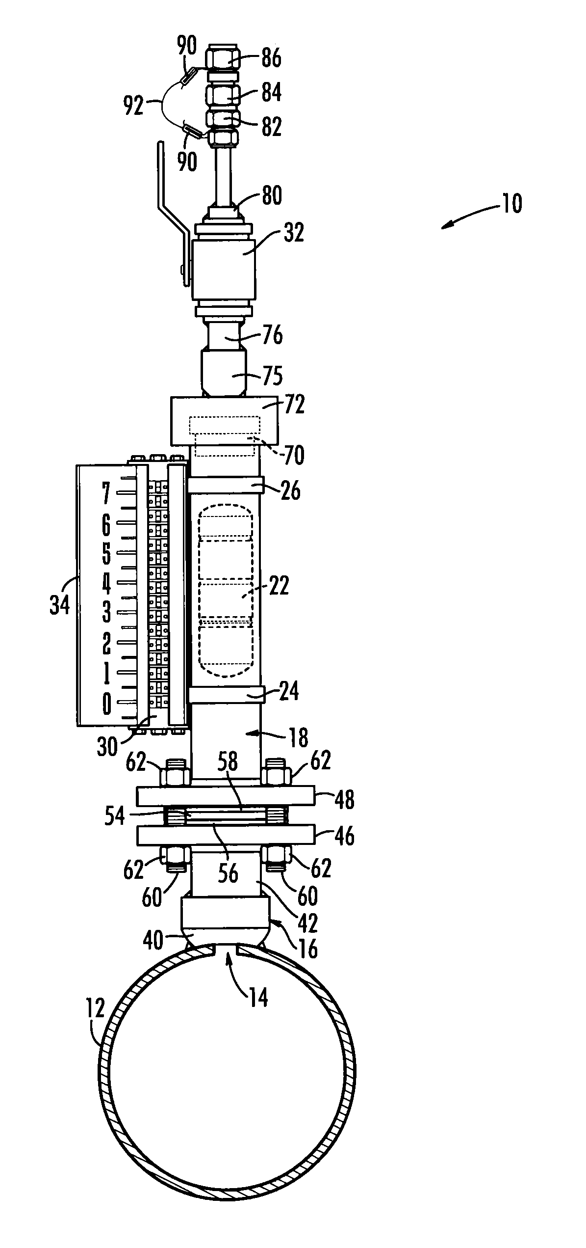
[0013]The present invention is directed to a gas accumulating, isolating, indicating and venting device, generally indicated by reference number 10 for use in a piping system. A system pipe 12 is shown in phantom lines in FIGS. 1 and 1B and is not part of the present invention but device 10 is intended to be used with system pipe 12.

[0014]For simplicity, the word gas will be used to indicate gas or gases.

[0015]Referring now to FIG. 1, device 10 includes a pipe fitting 16 that secures device 10 to system pipe 12, a standpipe 18 attachable to pipe fitting 16, a magnetic float 22 freely movable in vertically-oriented standpipe 18, and a corresponding indicator 30 external to standpipe 18 but which moves vertically with magnetic float 22 inside standpipe 18 as the level of fluid in standpipe 18 changes and responsively indicates that level by the position of indicator 30 on scale 34. Scale 34 carries a sequence of numbers. Indicator 30 may thus indicate the level of fluid in standpipe 1...


PUM


Abstract

A device for accumulating, isolating, indicating and venting accumulated gas in a fluid system pipe includes a main pipe fitting affixed to a system pipe in which a hole has been drilled. A stand pipe attached to the pipe fitting houses a magnetic float. A magnetic-float level indicator exterior to the pipe and responsive to the magnetic float indicates the magnetic float's level. A valve attached to the stand pipe above the magnetic float allows controlled ventilation of the gas in the standpipe and thus in the piping system. Gas from the system pipe accumulates in the standpipe, removed from the primary fluid flow path of the system pipe. In the standpipe, as the liquid/gas interface drops, the float drops to a pre-determined level, at which point the user vents the gas from the piping system, causing the magnetic float to rise to a level indicating that gas is again at acceptable levels in the piping system.

Description

PRIORITY CLAIM[0001]Priority is claimed to U.S. Provisional patent application Ser. No. 61 / 281,852, filed Nov. 23, 2009, which is incorporated herein in its entirety by reference.BACKGROUND OF THE INVENTION[0002]The present invention relates generally to the operation of fluid piping systems. More particularly, the present invention relates to keeping fluid piping systems free of air and other gases.[0003]Since the advent of commercial nuclear power in the late 1960's, the industry has been aware of issues regarding the accumulation of air and other gases in the high points in various safety-related fluid systems. These systems are designed to prevent nuclear fuel damage given various postulated accident scenarios. Air and gas accumulation in these fluid systems could result in failure of those systems and in their failure in turn to prevent fuel damage.[0004]The operators of nuclear power plants are required to demonstrate that they have suitable design, operational, and testing co...

Claims


Application Information

Patent Timeline
IPC IPC(8): F16K37/00
CPCF16K24/046F16K37/0033F16K37/005Y02E30/40G21D1/02G21C17/022G21C19/28Y02E30/00Y02E30/30Y10T137/3099Y10T137/8342
Inventor WOOD, JR., WILLIE TURNER
Owner NUCCORP
Why Eureka
Try Eureka