
Vehicle chassis with Anti-camber

a chassis and chassis technology, applied in the field of vehicle chassis with anti-camber, can solve the problems of undesirable crowning of the chassis, bending can be rather significant, and the inability to avoid a crown can be very difficult in the standard rv construction, so as to achieve the effect of improving the structural strength

Inactive Publication Date: 2011-05-26
THE SHYFT GRP INC
View PDF18 Cites 17 Cited by
  • Summary
  • Abstract
  • Description
  • Claims
  • Application Information

AI Technical Summary

Benefits of technology

[0009]Embodiments of the present invention provide new and improved vehicle chassis and particularly new and improved chassis for vehicles such as motor homes and busses. Embodiments of the invention provide improved structural strength while other embodiments provide improved starting points upon which the body of the vehicle can be constructed.
[0013]In a further embodiment, the chassis incorporates anti-camber preventing crowning of the chassis as a result of mounting an engine rearward of the rear axles of the vehicle. As such, in one embodiment, a vehicle chassis comprises a pair of spaced apart longitudinally extending center rails and an anti-camber fixing arrangement. The longitudinally extending center rails include anti-camber fixed therein. The anti-camber is such that prior to mounting an engine at a location rearward of a location of the chassis where a rear axle is mounted, the center rails have a vertically dished profile and after the engine has been mounted to the chassis, the degree of dishing is reduced. The anti-camber fixing arrangement fixes the anti-camber in the center rails prior to mounting the engine to the chassis.
[0016]Methods of adding the anti-camber to a chassis are also provided. In one embodiment, a method of forming a chassis unit including a chassis and an engine mounted rearward of a location at which rear axles of the chassis unit may be mounted is provided. The method includes bending first and second center rails to include anti-camber (i.e. a vertically downward dished shape). The method also includes fixing the anti-camber in the center rails such that the center rails have a dish shape in a longitudinal portion thereof. Further, the method includes operably mounting an engine to the center rails at a location rearward of a location of at least one rear axle mount. The step of mounting the engine removes the severity of the dish shape such that a top working platform defined, at least in part, by tops of the first and second center rail is substantially planar or is more planar than prior to the addition of the engine to the chassis.

Problems solved by technology

This ability to avoid a crown can be very difficult in standard RV construction.
This bending action will cause undesirable crowning of the chassis at a position between the front of the chassis and the rear axle(s).
Due to the significant weight of the engine and its components, this bending can be rather significant.
Merely increasing the size of individual structural members of the chassis may not be adequate to compensate for the bending as this can add undesirable weight and reduce volume for storage and other components of the RV.

Method used


Image

  • Vehicle chassis with Anti-camber
  • Vehicle chassis with Anti-camber
  • Vehicle chassis with Anti-camber

Examples


Embodiment Construction

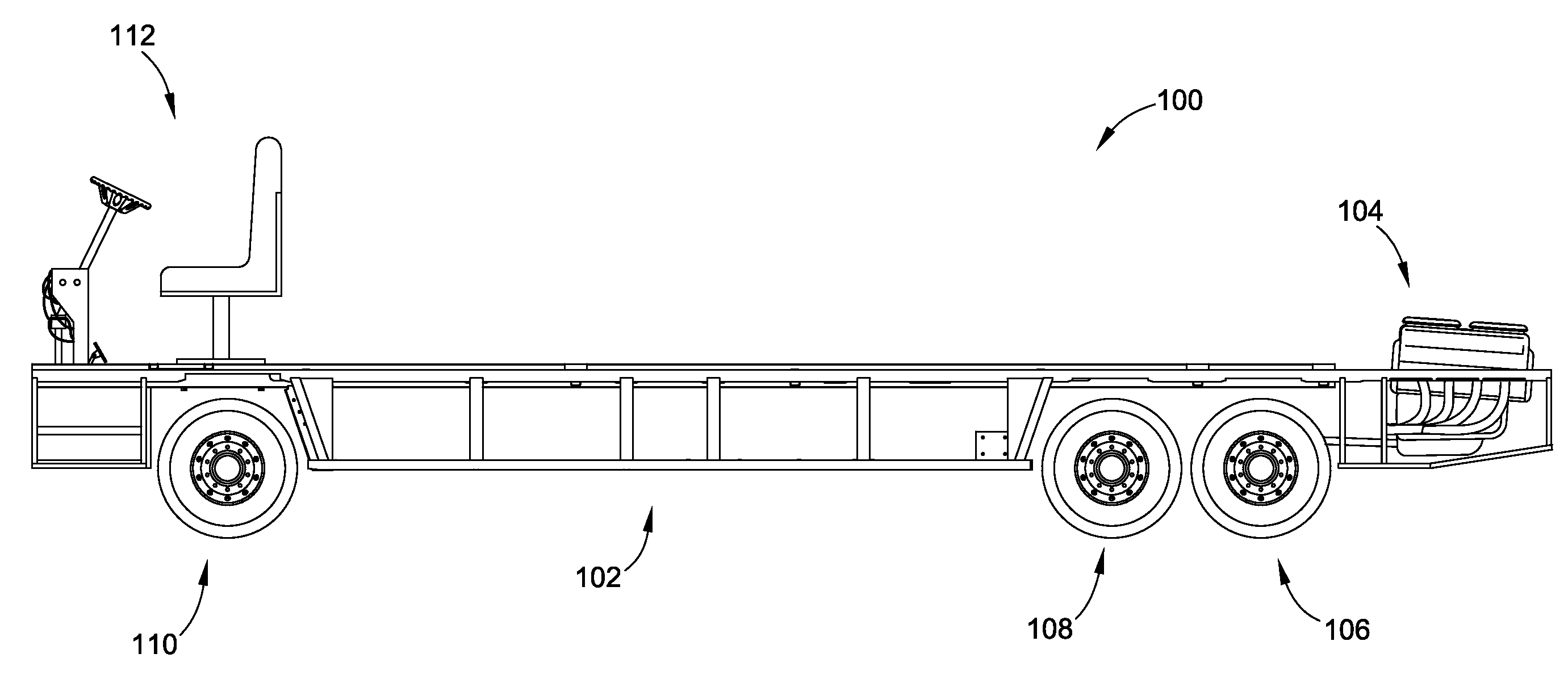
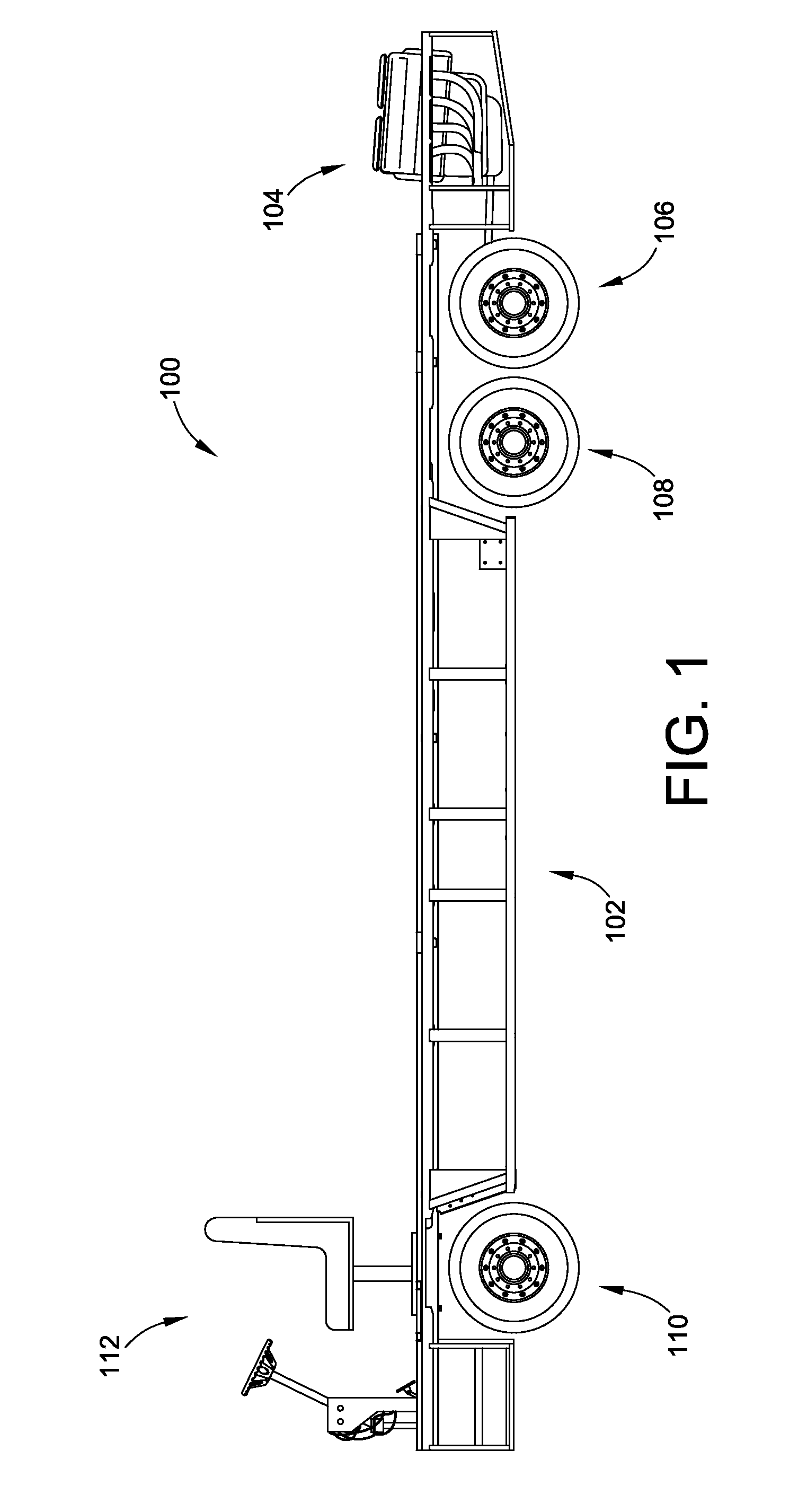
[0036]FIG. 1 is a left side photograph of rolling chassis 100 (i.e. modular chassis unit) for an RV that includes a chassis 102, an engine 104, rear axles 106, 108 (represented by the tires forming part of the drive train), a front axle 110 (which may or may not be axle in some embodiments and be provided by independent front suspension), and a driver station 112.

[0037]The rolling chassis 100 is fully functioning in an embodiment such that it can be driven. As such, a subsequent builder need only build the body (e.g. seating area for a bus or living quarters for an RV) to complete the vehicle.

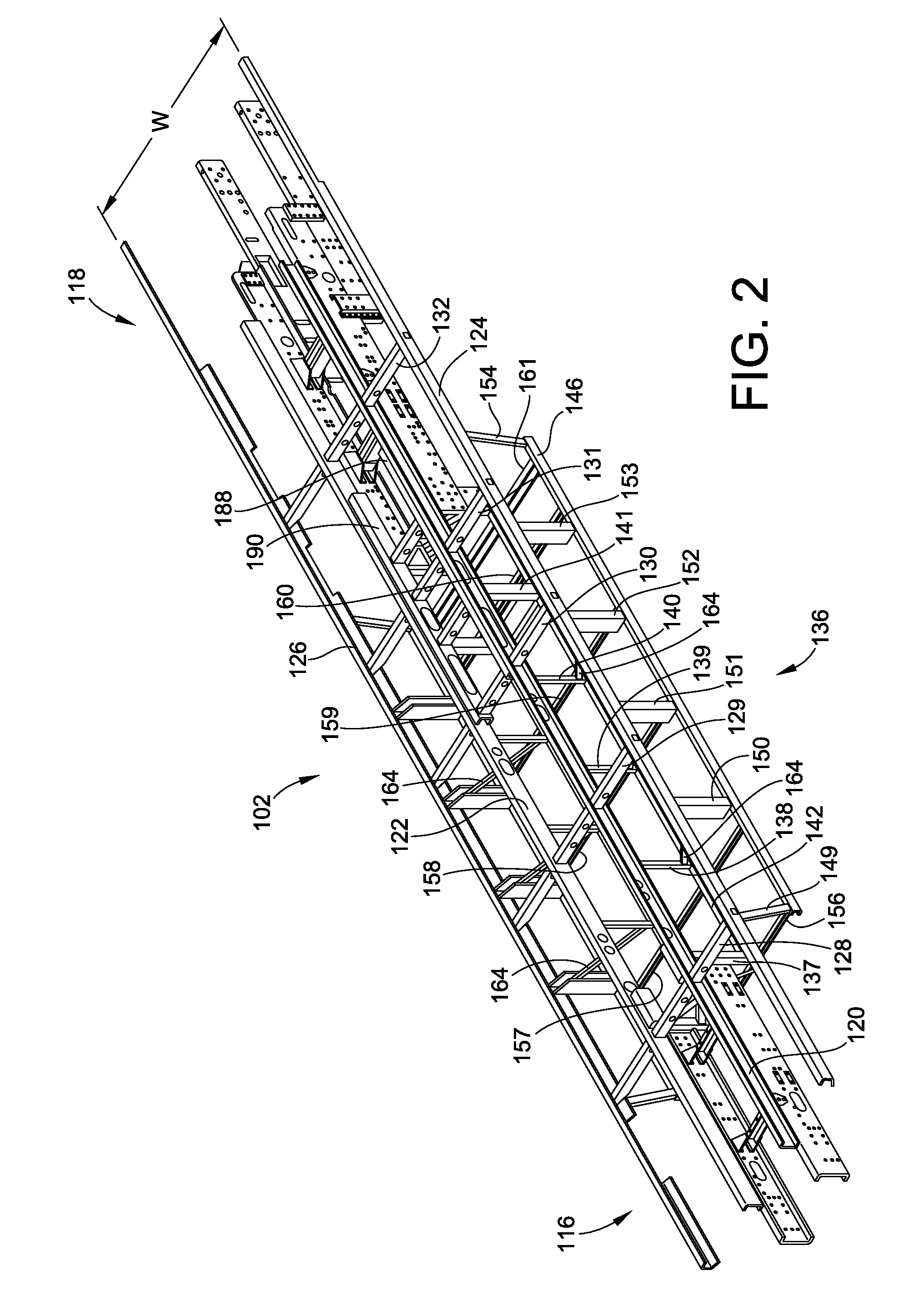
[0038]The chassis 102 is more clearly illustrated in the simplified top perspective illustration of FIG. 2. In FIG. 2, the front 116 of the chassis 102 is illustrated generally toward the left or bottom of the page and the rear 118 of the chassis 102 is illustrated generally toward the right or top of the page.

[0039]The chassis 102 generally includes a pair of center rails 120, 122. Center rail...


PUM

PropertyMeasurementUnit
heightaaaaaaaaaa
heightaaaaaaaaaa
heightaaaaaaaaaa

Abstract

A vehicle chassis for motor homes, busses and similar vehicles is provided. In an embodiment, the chassis includes anti-camber to counteract the bending action provided by the engine being mounted rear ward of the rear axle(s) of the vehicle such that the rear axle(s) act as a fulcrum causing crowning of the chassis. Further, embodiments of the invention utilize through the frame construction for lateral support members to increase storage space of a basement region and to increase strength of the welded joints of the various structural members.

Description

CROSS-REFERENCE TO RELATED PATENT APPLICATIONS[0001]This patent application claims the benefit of U.S. Provisional Patent Application No. 61 / 264,493, filed Nov. 25, 2009, the entire teachings and disclosure of which are incorporated herein by reference thereto.FIELD OF THE INVENTION[0002]This invention generally relates to motor home and bus chassis.BACKGROUND OF THE INVENTION[0003]Standard construction of a motor home or bus (generally referred to herein as a “recreation vehicle” or “RV”) requires construction of a chassis that may typically provide the mechanical workings of the RV. The chassis will typically house the suspension, the engine and drive train. The chassis will also operably support a body that will include a living environment including among other things a plurality of passenger seats in a bus or a living area in a motor home.[0004]Often, the chassis and the mechanical workings of the RV may be formed as a modular unit that are then provided to a separate manufactu...

Claims


Application Information

Patent Timeline
Patent Type & Authority Applications(United States)
IPC IPC(8): B62D21/02B23P11/00
CPCB62D21/02B62D31/02B62D47/02Y10T29/49622B62D21/08B62D65/00B62D21/20
Inventor OLSON, TERRY KYLEENGELBRECHT, ROY FRANK
Owner THE SHYFT GRP INC
Learn More