LED Base Structure with Embedded Capacitor

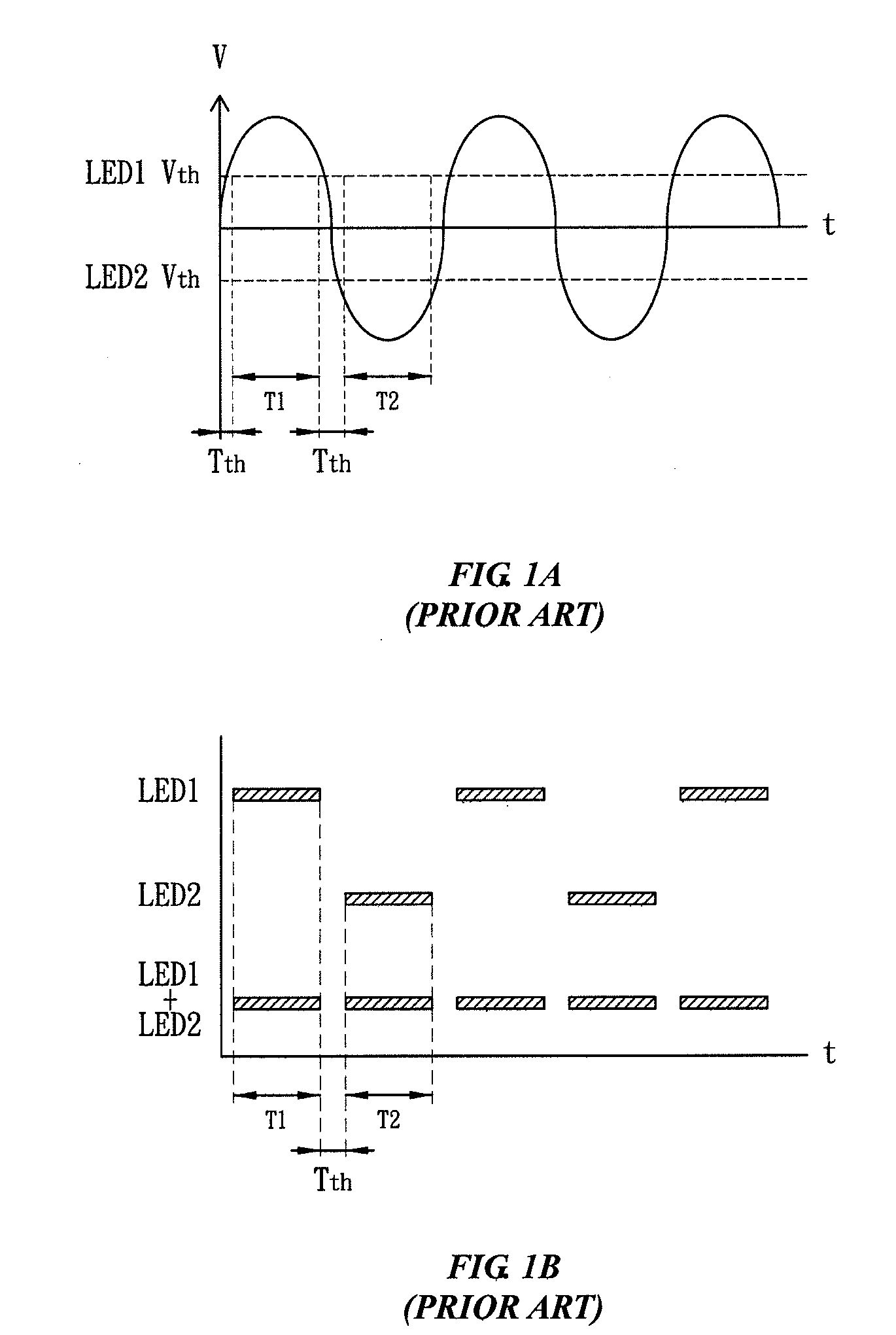
a technology of led base structure and capacitor, which is applied in the direction of discharge tube luminescnet screen, discharge tube/lamp details, electric discharge lamps, etc., can solve the problems of light-emitting diodes ledb>1/b>, b>2/b> having rather limited application in an ac power environment, etc., to prevent leds from flashing, reduce costs, and high performance and practicability

Inactive Publication Date: 2011-05-26
HELIO OPTOELECTRONICS
View PDF4 Cites 5 Cited by
  • Summary
  • Abstract
  • Description
  • Claims
  • Application Information

AI Technical Summary

Benefits of technology

[0013]It is an objective of the present invention to overcome the existing drawbacks of a conventional light-emitting diode (LED) base structure by providing a novel LED base structure with an embedded capacitor. The technical issue to be addressed by the present invention involves embedding two metal layers inside the body of an LED and forming a dielectric layer therein so as to form an embedded capacitor, couple together the embedded capacitor and an external resistor, and form a resistor-capacitor delay circuit. If a plurality of LEDs are coupled to an LED base structure and supplied with AC power, the known problem with LEDs flashing arising from alteration of polarity of voltage of AC power can be eliminated when the time of switching on the LEDs is controlled by the delay circuit.
[0021]The present invention excels the prior art in advantages and beneficial effects. Given the aforesaid technical solution as disclosed in the present invention, the LED base structure with an embedded capacitor at least has the following advantages and beneficial effects:
[0023]2. The step of embedding a capacitor in the LED base structure is performed during the LED base structure fabrication process, thereby cutting costs and allowing capacitance to be designed as needed.
[0025]In conclusion, an LED base structure with an embedded capacitor, as disclosed in the present invention, comprises a body, at least one pair of metal layers, at least one dielectric layer, and at least two conductive channels. The body is an insulating base. The metal layers are disposed in the body, and the dielectric layer is disposed between the metal layers, so as to form an embedded capacitor. The conductive channels are electrically connected to the metal layers, respectively. The LED base structure is further electrically connected to a resistor for forming a resistor-capacitor delay circuit whereby a phase delay is effectuated whenever AC power is supplied to the LED base structure, so as to control the time for switching on one of two parallel-connected LEDs and, as a result, prevent the LEDs from flashing which might otherwise arise when the LEDs are supplied with AC power. The present invention has the aforesaid advantages and practical values, improves on the prior art in terms of product structure and function, makes significant progress in technology, manifests high performance and practicability, and demonstrates inventive and remarkable functionality. Accordingly, an LED base structure with an embedded capacitor according to the present invention has novelty, non-obviousness, and practicability.

Problems solved by technology

As a result, LEDs have rather limited application.
As a result, the light-emitting diodes LED1, LED2 have rather limited application in an AC power environment.
Therefore, the conventional LED base structure is inconvenient and defective in terms of structure and use and thus has room for improvement.
However, on the one hand, applicable designs have hitherto not been developed and finalized.
On the other hand, general products lack an appropriate structure required for solving the aforesaid problems.

Method used


Image

  • LED Base Structure with Embedded Capacitor
  • LED Base Structure with Embedded Capacitor
  • LED Base Structure with Embedded Capacitor

Examples


Embodiment Construction

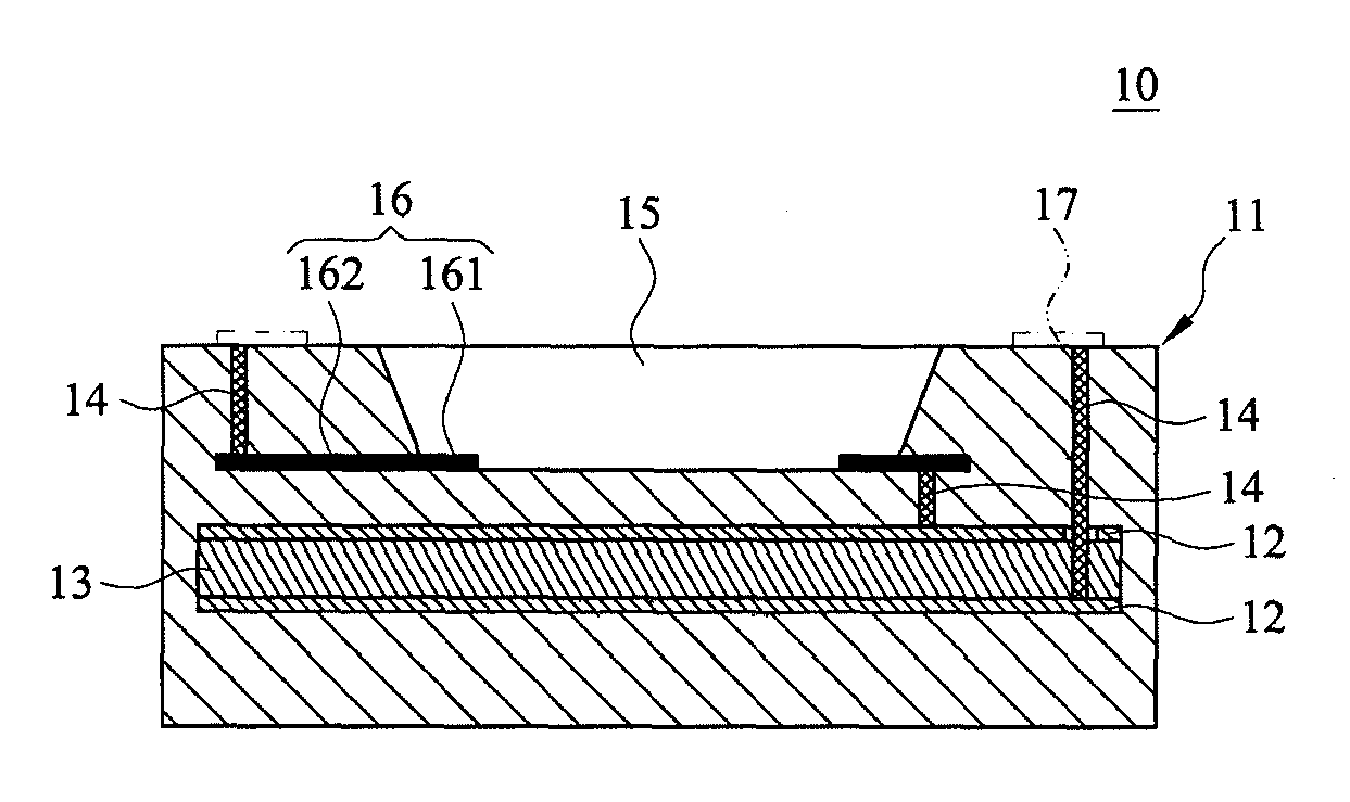
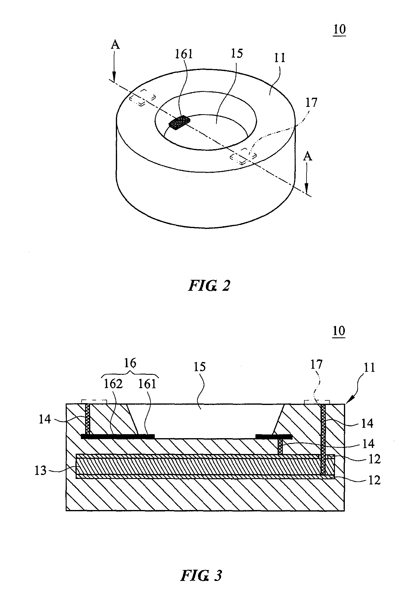
[0036]To further describe the technical means adopted in the present invention to achieve the objectives of the present invention and the effects of the technical means adopted, the specific aspects of implementation, structure, features, and effects of a light-emitting diode (LED) base structure with an embedded capacitor put forth according to the present invention are illustrated in detail with a preferred embodiment and accompanying drawings hereunder.

[0037]The above and other technical contents, features, and effects of the present invention can be clearly presented in detail when described with a preferred embodiment and accompanying drawings hereunder. A description of the specific aspects of implementation of the present invention enables deeper thorough understanding of the technical means adopted in the present invention to achieve the objectives of the present invention and the effects of the technical means adopted. However, the accompanying drawings serve reference and ...


PUM


Abstract

An LED base structure with an embedded capacitor includes a body, at least one pair of metal layers, at least one dielectric layer, and at least two conductive channels. The body is an insulating base. The metal layers are disposed in the body, and the dielectric layer is disposed between the metal layers, so as to form an embedded capacitor. The conductive channels are electrically connected to the metal layers, respectively. The LED base structure is further electrically connected to a resistor for forming a resistor-capacitor delay circuit whereby a phase delay is effectuated whenever AC power is supplied to the LED base structure, so as to control the time for switching on one of two parallel-connected LEDs and, as a result, prevent the LEDs from flashing which might otherwise arise when the LEDs are supplied with AC power.

Description

CROSS-REFERENCE TO RELATED APPLICATIONS[0001]This application is a 35 USC 371 application of PCT / CN2008 / 001453 filed on Aug. 12, 2008, published as Pub. No. WO2010 / 017655. The content of the specification is incorporated herein by reference.BACKGROUND OF THE INVENTION[0002]1. Technical Field[0003]The present invention relates to light-emitting diode (LED) base structures each with an embedded capacitor, and more particularly, to an LED base structure equipped with an embedded capacitor and configured to use alternating current (AC) as a power source.[0004]2. Description of Related Art[0005]Development of light-emitting diode (LED) technology is swift and sophisticated. Also, LEDs have advantages, such as low volume, low power consumption, high reaction rate, long service life, and high vibration resistance. Hence, LEDs are gradually replacing traditional halogen lamps and fluorescent tubes and therefore have obviously become a new light source for use with future lighting devices.[0...

Claims


Application Information

Patent Timeline
Patent Type & Authority Applications(United States)
IPC IPC(8): H01J1/62
CPCH01L25/0753H01L25/167H01L33/486H01L33/62H01L2924/0002H05B33/0821H01L2924/00H05B45/42
Inventor CHEN, MING-HUNGWEN, SHIH-YICHEN, JING-YI
Owner HELIO OPTOELECTRONICS
Why Eureka
Try Eureka