Filament for fluorescent lamp

a fluorescent lamp and filament technology, applied in the field of filament for fluorescent lamps, can solve the problems of reducing the width of the electrode, the limit of increasing the lifespan of the fluorescent lamp, and the probability of early deterioration and early blackening of the fluorescent substance, so as to increase the lifespan of the fluorescent lamp, and increase the remaining amount of the emitter

Inactive Publication Date: 2011-05-26
KUMHO ELECTRIC INC
View PDF5 Cites 0 Cited by
  • Summary
  • Abstract
  • Description
  • Claims
  • Application Information

AI Technical Summary

Benefits of technology

[0014]According to a filament for a fluorescent lamp in accordance with an exemplary embodiment of the present invention, an emitter can also be applied to a space between a core region and a coil of the filament, to which the emitter could not be applied in the conventional filament so that an application amount of the emitter is increased three times or more, and an outer coil and an inner coil of the filament are configured to form a lattice structure and electrically connected with each other such that, even when the coil is cut, the fluorescent lamp can be lit. Thereby, the lifespan of the fluorescent lamp can be increased.
[0015]Further, a cold resistance Rc and a heat resistance Rh of the filament can be optimized to maintain the temperature of the filament at 795 to 1043° C., and thus, scattering and evaporation of the emitter generated from the filament can be suppressed to increase the remaining amount of the emitter. Thereby the lifespan of the fluorescent lamp can be increased.

Problems solved by technology

However, as shown in FIG. 2, in the conventional filament 1, since the emitter 4 cannot be applied to a space S2 between a core region S1 and a coil, there is a limit in increasing the lifespan of the fluorescent lamp.
In this case, a load exerted to a wall of the tube is increased, leading to an increased probability of early deterioration and early blackening of the fluorescent substance, and the width of an electrode is reduced, leading to a decrease in the emitter material to be applied.

Method used


Image

  • Filament for fluorescent lamp
  • Filament for fluorescent lamp
  • Filament for fluorescent lamp

Examples


Embodiment Construction

[0025]Hereinafter, a media separating device of an automatic media dispenser according to a preferred embodiment of the present invention will be described in detail with reference to the accompanying drawings.

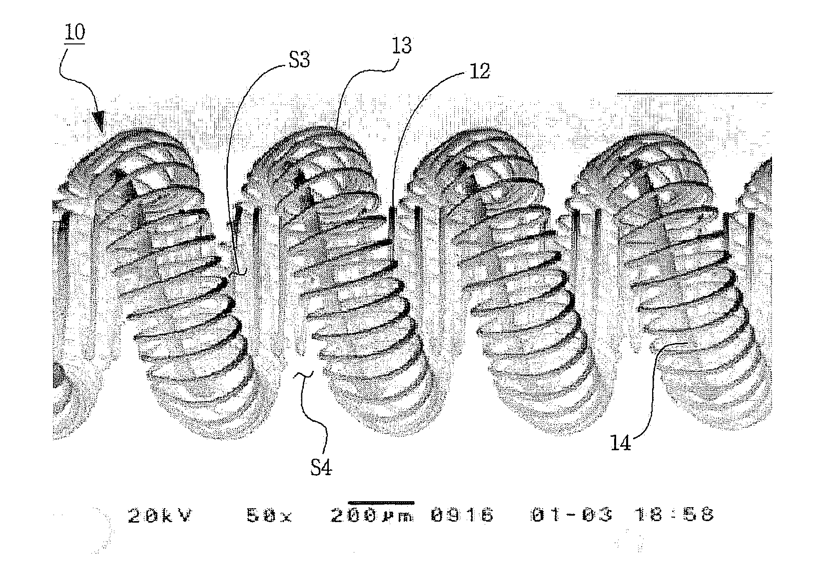
[0026]FIG. 4 is a SEM image of a filament 10 according to the present invention. FIG. 5 is a SEM image of the filament 10 shown in FIG. 4, to which an emitter such as barium oxide (BaO), calcium oxide (CaO) or strontium oxide (SrO), etc., is applied. Hereinafter, the above filament will be referred to as a triple filament.

[0027]As shown in FIG. 4, the filament 10 according to the present invention comprises an inner coil 12, an outer coil 13 and a core wire 14 passed through the outer coil 13. In particular, the inner coil 12 is wound in a spiral shape in one direction, the core wire 14 is wound in a spiral shape and surrounds the inner coil 12 in a longitudinal direction of the inner coil 12. And, the outer coil 13 is wound in a spiral shape and surrounds the core wire 14 sur...


PUM


Abstract

The present invention relates to a filament for a fluorescent lamp, having a structure that can increase an amount of emitter applied thereto, and having optimized cold resistance (Rc) and a heat resistance (Rh) which capable of recognizing appropriate temperature thereof by which evaporation or scattering of the emitter can be decreased and maintaining a temperature thereof within an appropriate range, thereby reducing a loss rate of the emitter applied to the filament to increase the lifespan of the fluorescent lamp. The filament includes an inner coil wound in a spiral shape in one direction, a core wire wound in a spiral shape to surround the inner coil in a longitudinal direction of the inner coil, and an outer coil wound in a spiral shape to surround the core wire and surrounding the inner coil together with the core wire and characterized in that a ratio (Rh/Rc) between a heat resistance Rh and a cold resistance Rc of the filament is 4.8 to 6.2.

Description

TECHNICAL FIELD[0001]The present invention relates to a filament for a fluorescent lamp, and more particularly, to a filament for a fluorescent lamp, having a structure that can increase an amount of emitter applied thereto, and having optimized cold resistance (Rc) and a heat resistance (Rh) which capable of recognizing appropriate temperature thereof by which evaporation or scattering of the emitter can be decreased and maintaining a temperature thereof within an appropriate range, thereby reducing a loss rate of the emitter applied to the filament to increase the lifespan of the fluorescent lamp.BACKGROUND ART[0002]Fluorescent lamps are light sources in which ultraviolet light generated by discharge excites a fluorescent substance to generate visible rays, and have widely been used not only for general lighting but also as light sources for backlight units of liquid crystal displays (LCDs) in recent times.[0003]In general, a fluorescent lamp includes a glass tube having an inner ...

Claims


Application Information

Patent Timeline
Patent Type & Authority Applications(United States)
IPC IPC(8): H01J61/04
CPCH01J61/0672
Inventor KIM, BYUNG-HYUN
Owner KUMHO ELECTRIC INC
Why Eureka
Try Eureka