Two-wire analog fet-based dimmer switch

a dimmer switch and analog technology, applied in the field of load control devices, can solve the problems of increasing the cost of prior art fet-based reverse phase control dimmer switches, load to illuminate, and high-efficiency light sources typically consume less power and provide longer operational li

Active Publication Date: 2011-05-26
LUTRON TECH CO LLC
View PDF44 Cites 61 Cited by
  • Summary
  • Abstract
  • Description
  • Claims
  • Application Information

AI Technical Summary

Benefits of technology

[0017]According to an embodiment of the present invention, a load control device (such as, for example, a dimmer switch) for controlling the amount of power delivered from an AC power source to an electrical load comprise a bidirectional semiconductor switch having first and second anti-series connected switching transistors (e.g., field-effect transistors) that are adapted to be coupled between the source and the load, and are controlled to be conductive and non-conductive in a complementary b

Problems solved by technology

However, prior art reverse phase-control dimmer switches have either required neutral connections and/or advanced control circuits (such as microprocessors) for controlling the operation of the FETs.
These advanced control circuits and power supplies add to the cost of prior art FET-based reverse phase-control dimmer switches (as compared to analog forward phase-control dimmer switches).
If the power rating of the lighting load is too low, the charging current conducted by the power supply through the lighting load may be great enough to cause the lighting load to illuminate to a level that is perceptible to the human eye when the lighting load is off.
High-efficiency light sources typically consume less power and provide longer operational lives as compared to incandescent and halogen lamps.
However, the load regulation devices for the high-efficiency light sources may have high input impedances or input impedances that vary in magnitude throughout a half-cycle.
Therefore, when a prior-art forward phase-control dimmer switch is coupled between the AC power source and the load regulation device for the high-efficiency light source, the load control

Method used


Image

  • Two-wire analog fet-based dimmer switch
  • Two-wire analog fet-based dimmer switch
  • Two-wire analog fet-based dimmer switch

Examples


first embodiment

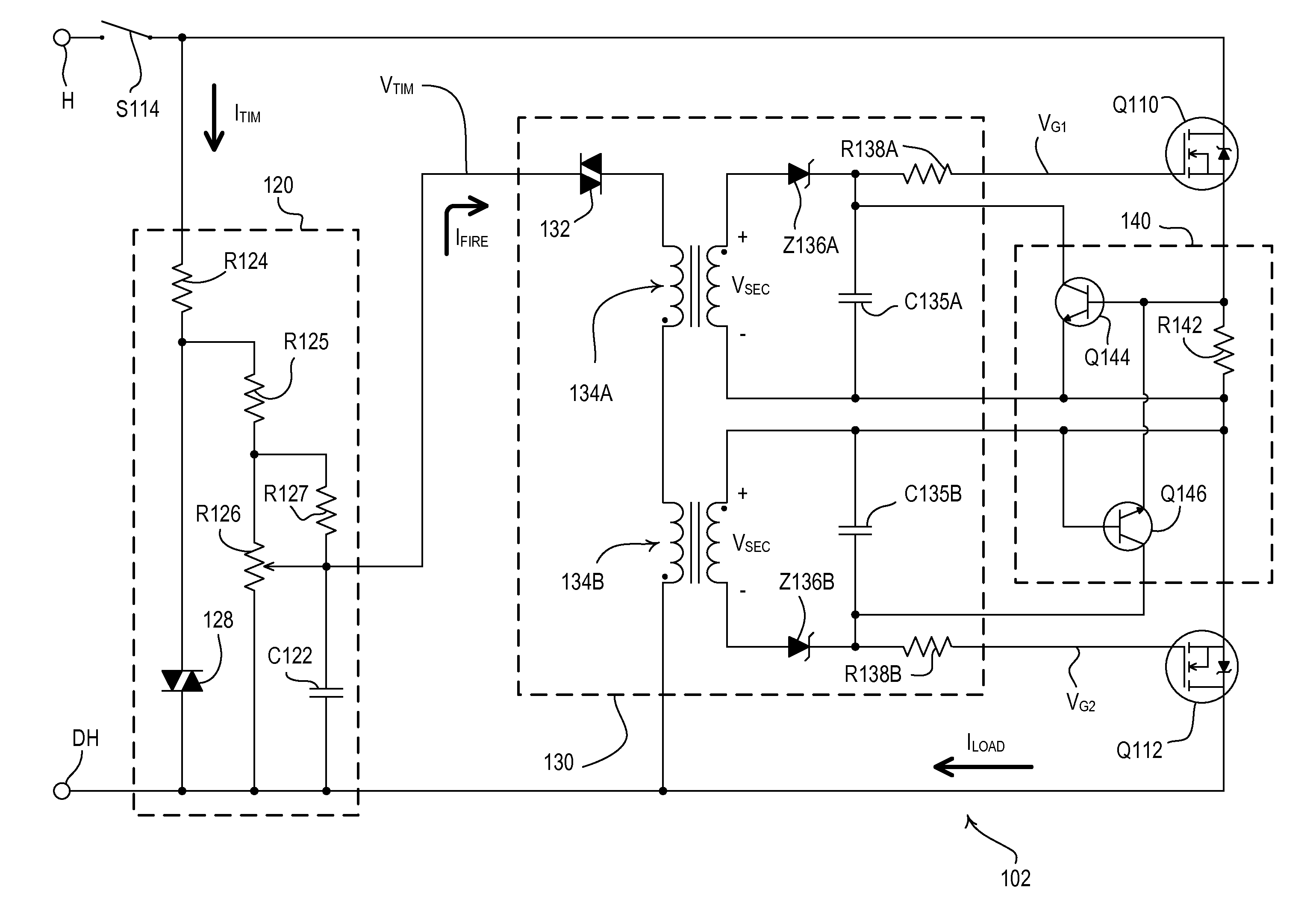
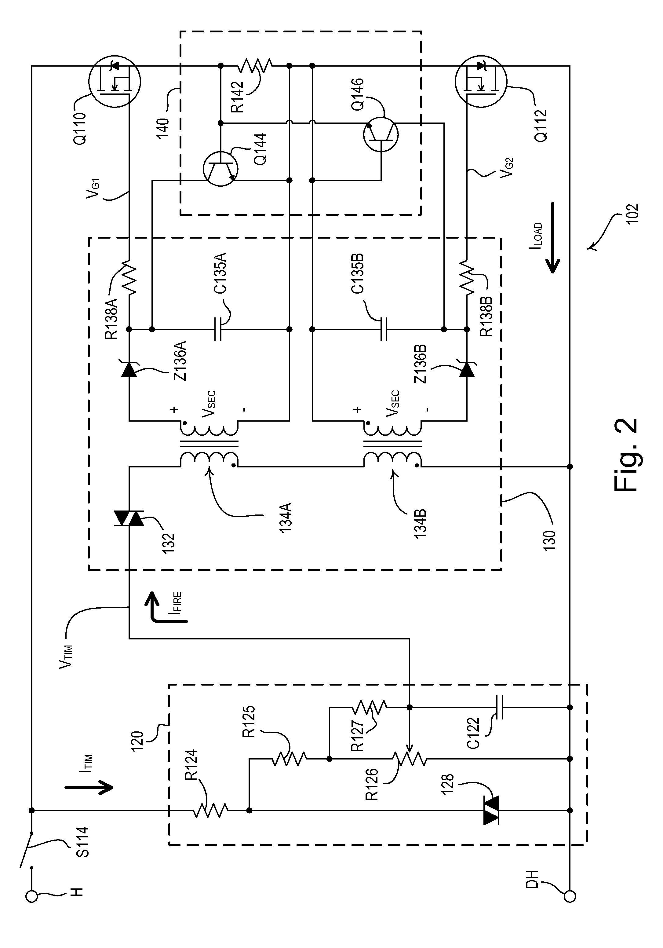
[0036]FIG. 2 is a simplified schematic diagram of the dimmer switch 102 according to the present invention. The dimmer switch 102 comprises a bidirectional semiconductor switch having two individual switching transistors, e.g., two field-effect transistors (FETs) Q110, Q112, coupled in anti-series connection between the hot terminal H and the dimmed hot terminal DH for control of the amount of power delivered to the LED driver 104. The FETs Q110, Q112 have control inputs (i.e., gates) that receive respective gate voltages VG1, VG2 and channel regions that are rendered conductive and non-conductive in response to the respective gate voltages VG1, VG2. Specifically, the FETs Q110, Q112 are rendered conductive when the magnitudes of the respective gate voltages VG1, VG2 are controlled to a nominal gate voltage VN (e.g., approximately 9 V) and are rendered non-conductive when the magnitudes of the respective gate voltages VG1, VG2 are controlled to approximately zero volts. The FETs Q11...

second embodiment

[0046]FIG. 4 is a simplified schematic diagram of a dimmer switch 202 according to the present invention. The dimmer switch 202 comprises a drive limit circuit 250, which is coupled in series with the diac 132 and the primary windings of the two pulse transformers 134A, 134B of the drive circuit 130. The drive limit circuit 250 operates to limit the number of times that the drive circuit 130 attempts to render the FETs Q110, Q112 conductive during a specific half-cycle. For example, if the overcurrent protection circuit 140 renders one of the FETs Q110, Q112 non-conductive, the drive limit circuit 250 prevents the drive circuit 130 from attempting to render the respective FET conductive again during the present half-cycle.

[0047]When the diac 132 fires each half-cycle, the drive limit circuit 250 conducts the firing current IFIRE and generates an offset voltage VOFFSET across a capacitor C252A during the positive half-cycles and a capacitor C252B during the negative half-cycles. The ...


PUM

PropertyMeasurementUnit
Electric potential / voltageaaaaaaaaaa
Timeaaaaaaaaaa
Poweraaaaaaaaaa

Abstract

A two-wire load control device, such as, a dimmer switch, for controlling the amount of power delivered from an AC power source to an electrical load comprise a bidirectional semiconductor switch having first and second anti-series connected switching transistors (such as, for example, field-effect transistors) that are adapted to be coupled between the source and the load, and are controlled to be conductive and non-conductive in a complementary basis. The bidirectional semiconductor switch is operable to be rendered conductive and to remain conductive independent of the magnitude of a load current conducted through semiconductor switch. The dimmer switch also comprises a drive circuit for rendering the first and second switching transistors conductive and non-conductive each half-cycle on the complementary basis, so as to control the amount of power delivered to the electrical load to a desired amount of power.

Description

[0001]This application is related to commonly-assigned U.S. Provisional Patent Application No. 61 / 264,528, filed Nov. 25, 2009, and U.S. Provisional Patent Application No. 61 / 333,050, filed May 10, 2010, both entitled TWO-WIRE ANALOG DIMMER SWITCH FOR LOW-POWER LOADS, the entire disclosures of which are hereby incorporated by reference.BACKGROUND OF THE INVENTION[0002]1. Field of the Invention[0003]The present invention relates to load control devices for controlling the amount of power delivered to an electrical load, and more particularly, to a two-wire analog dimmer switch that has substantially no minimum load requirement and comprises two anti-series-connected field-effect transistors (FETs) that are controlled in a complementary basis.[0004]2. Description of the Related Art[0005]Prior art two-wire dimmer switches are coupled in series electrical connection between an alternating-current (AC) power source and a lighting load for controlling the amount of power delivered from th...

Claims


Application Information

Patent Timeline
IPC IPC(8): H03K17/94H03K17/56
CPCH05B39/04Y02B20/148H05B39/048Y02B20/00
Inventor SALVESTRINI, CHRISTOPHER JAMES
Owner LUTRON TECH CO LLC
Why Eureka
Try Eureka