Method of measuring earth ground resistance of a pylon

a technology of earth ground resistance and pylon, which is applied in the direction of earth resistance measurement, resistance/reactance/impedence, and impedence measurement, etc., can solve the problems of harmonic distortion, unintended path, and increase the risk of equipment failur

Inactive Publication Date: 2011-05-26
JOHN FLUKE MFG CO INC
View PDF8 Cites 16 Cited by
  • Summary
  • Abstract
  • Description
  • Claims
  • Application Information

AI Technical Summary

Benefits of technology

[0021]In yet another embodiment, the testing device is preferably adapted for the storage of measurement data. This enables multiple measurements to be taken for an individual footing, an individual pylon, or a plurality of pylons connected in a given line or grid. This enables an operator to decide when enough data for sufficient accuracy has been gathered, wherein after the last selective measurement has been made (either for an individual pylon or plurality of pylons), the overall resistance and / or impedance of the pylon, the resistance and / or impedance of each footing, and the overall resistance and / or impedance of all pylons which are connected in parallel via an earth cable, may be calculated in a simple manner.

Problems solved by technology

A lack of good grounding is undesirable and increases the risk of equipment failure.
The absence of an effective grounding system can lead to various problems, such as instrumentation errors, harmonic distortion issues, power factor problems and a host of possible intermittent dilemmas.
If fault currents have no path to the ground through a properly designed and maintained grounding system, they will find unintended paths.
Over time, corrosive soils with high moisture content, high salt content, and high temperatures can degrade ground rods and their connections.
So although the ground system may have had low ground resistance values when initially installed, the resistance of the grounding system can increase if the ground rods, or other elements of the grounding system, corrode over time.
Such differences may indicate a failure (i.e. excessive corrosion or damage) of one or more footings.
Such adaptors tend to not only be expensive, but also bulky, thus increasing the amount of equipment needed to be transported to a pylon measurement site.
Furthermore, such prior art systems are limited to pylons with a maximum of four footings.
Since many pylons have additional earth ground rods and footings requiring a minimum of five or more measurements, prior art techniques are unable to provide an effective system for accommodating the measurement of further footings or ground rods.
By not taking measurements of the supplemental elements of a pylon grounding system into account, this can lead to inaccurate values for the overall resistance of the pylon.
Furthermore, prior art systems also fail to provide a true value for the resistance of the pylon footings.
Also, prior art techniques tend to be extremely time consuming, labor-intensive and costly since it is necessary for current clamps to be connected to each of the plurality of earth ground rods (i.e. footings) to be connected to the testing means, which also need to be connected to an adaptor.

Method used


Image

  • Method of measuring earth ground resistance of a pylon
  • Method of measuring earth ground resistance of a pylon
  • Method of measuring earth ground resistance of a pylon

Examples


Embodiment Construction

[0034]It is to be understood by one of ordinary skill in the art that the present discussion is a description of exemplary embodiments only, and is not intended as limiting the broader aspects of the present invention, which broader aspects are embodied in the exemplary constructions.

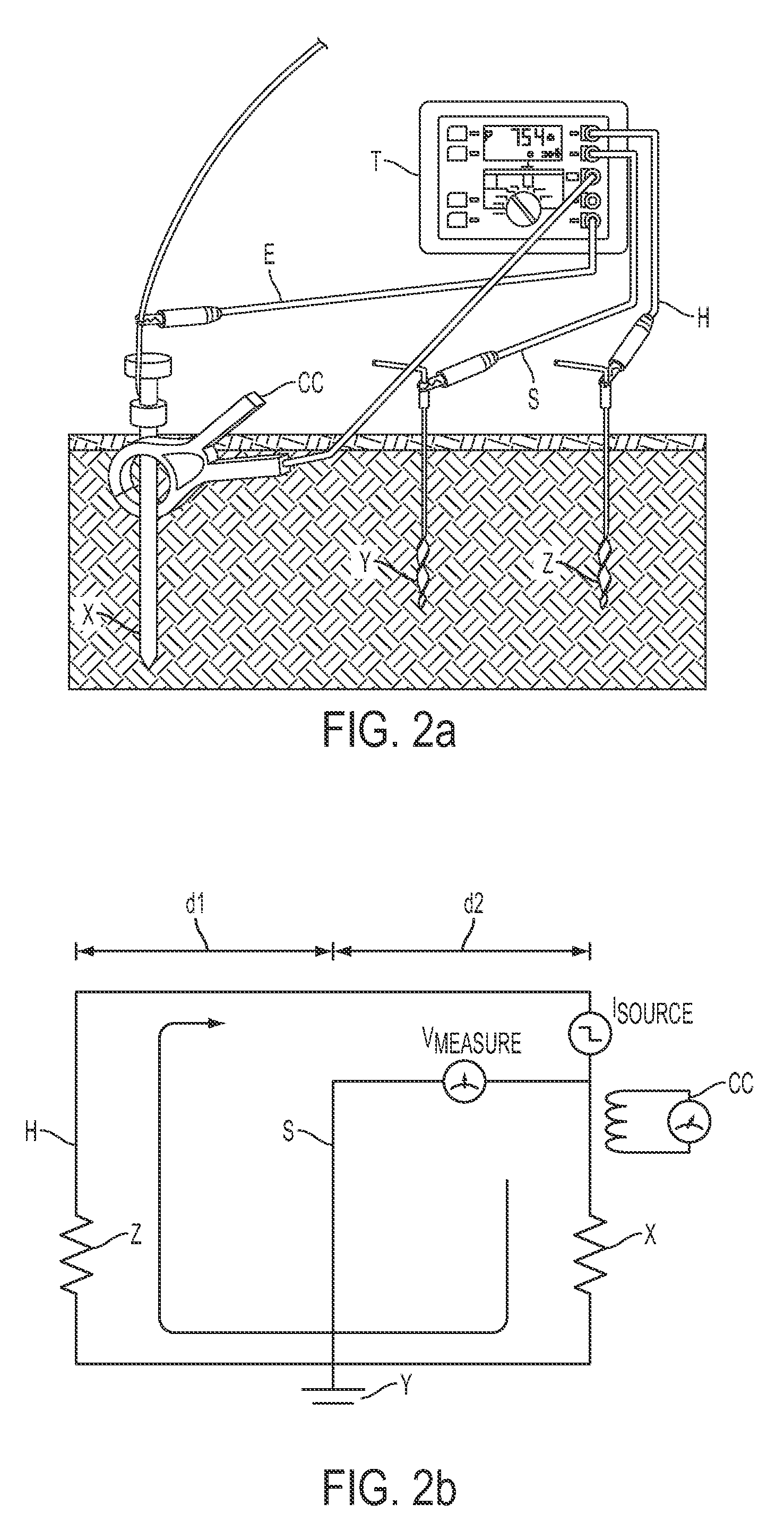
Selective Measurement

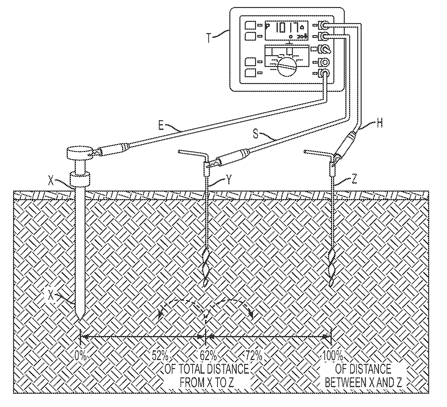
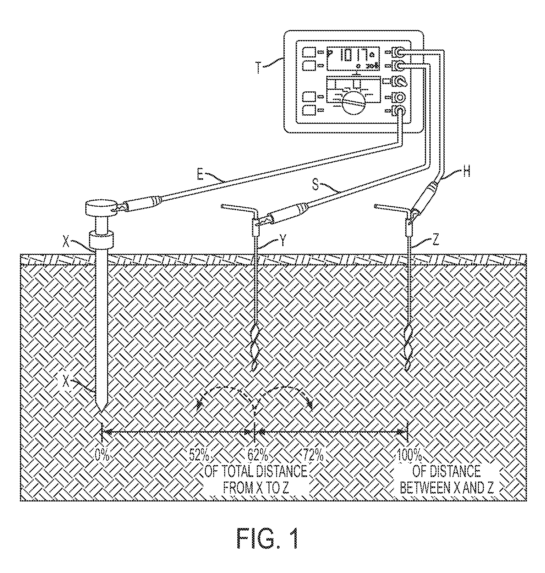
[0035]Referring now to FIG. 2a, an example of a “selective measurement testing” technique in accordance with the present invention is implemented. This is akin to “fall-of-potential” testing which is used to measure the ability of an earth ground system or an individual electrode to dissipate energy from a pylon, since it provides all the same measurements as those resulting from the fall-of-potential technique. Selective measurements are also advantageously obtained in a more efficacious way than fall-of-potential testing, since it is not necessary to disconnect an individual earth electrode to be tested from its connection to the pylon grounding system. Such disconnection would un...


PUM


Abstract

The present invention relates generally to a facilitated method for accurately measuring the earth ground resistance of a ground rod, in particular a footing of a pylon acting as a ground rod or a ground rod attached to the footings of a pylon, and obtaining an overall value for the resistance of the pylon i.e. all footings in parallel, and all pylons connected in parallel thereto. A method of determining the earth ground resistance of two or more pylon footings is provided according to the present invention, comprising conducting selective measurements of each footing of a pylon consecutively and wherein true values for the resistance of each footing measured are calculated. According to the present invention the testing means is connected directly to two auxiliary electrodes which are placed at predetermined distances from the pylon, and a current measurement means which is placed around a pylon footing in order to measure a the current flowing along the footing.

Description

FIELD OF THE INVENTION[0001]The present invention relates generally to a facilitated method for accurately measuring the earth ground resistance of a ground rod, such as a footing of a pylon acting as a ground rod or a ground rod attached to the footings of a pylon.BACKGROUND[0002]A lack of good grounding is undesirable and increases the risk of equipment failure. The absence of an effective grounding system can lead to various problems, such as instrumentation errors, harmonic distortion issues, power factor problems and a host of possible intermittent dilemmas. If fault currents have no path to the ground through a properly designed and maintained grounding system, they will find unintended paths. Furthermore, a good grounding system is also used to prevent damage to industrial plants and equipment and is therefore necessary in order to improve the reliability of equipment and reduce the likelihood of damage due to lightning or fault currents.[0003]Over time, corrosive soils with ...

Claims


Application Information

Patent Timeline
Patent Type & Authority Applications(United States)
IPC IPC(8): G01R27/08
CPCG01R31/025G01R27/20G01R27/08G01R27/18
Inventor LAEPPLE, KLAUS
Owner JOHN FLUKE MFG CO INC
Why Eureka
Try Eureka