System and Method for Determining Poses of Objects

a technology of object pose and system, applied in the field of computer vision systems, can solve the problems of human intervention, suboptimal performance, damage to the robot arm or object, etc., and achieve the effect of improving the accuracy of object stacking

Active Publication Date: 2011-05-26
MITSUBISHI ELECTRIC RES LAB INC
View PDF4 Cites 31 Cited by
  • Summary
  • Abstract
  • Description
  • Claims
  • Application Information

AI Technical Summary

Problems solved by technology

Any deviations can result in suboptimal performance, or even damage to the robotic arm or object.
However, deployment of computer vision enabled robots continues to be limited because of numerous technical difficulties.
Systems have been designed to pick stacked objects, but the precise stacking of objects also needs a complex mechanical system, or human intervention.
Most computer vision systems lack reliability, accuracy and robustness and use expensive sensors and hardware.
Current systems lack the capability of picking objects that are randomly arranged in a haphazard manner on top of each other in a pile or in a bin.
The problem of object picking is not new.
These systems are expensive, lack inter-operability because they need to be designed specifically for each object, and cannot handle objects randomly arranged in a bin.
Most 2D computer vision systems can locate the in-plane orientation and location of objects object but cannot determine the out of plane rotation and distance to the object.
Thus, those systems cannot operate on random pile of objects, or a bin of objects.
However, those systems cannot determine the out of plane rotation, and are often unreliable in their depth estimate.
However, finding corresponding features is a challenging problem, especially for machine objects, which are often shiny and have a homogeneous featureless texture.
In addition, stereo vision systems have a high degree of sensitivity to noise during feature localization.
Another problem with stereo systems is that the depths are only recovered at the feature points, and not for the entire object.
The reduced accuracy can be tolerated for certain applications such as unracking large body panels in body shops, but not for accurate bin picking of small objects with mirror like surfaces.
Laser systems have not been commercialized successfully for general random bin picking.
In addition, the use of lasers also leads to safety issues when deployed in close proximity of operators.
However, that system only tries to find unoccluded objects in the scene and has difficulties when a large portion of the object is occluded.
That system also requires an additional segmentation step, which can itself be prone to error.

Method used


Image

  • System and Method for Determining Poses of Objects
  • System and Method for Determining Poses of Objects
  • System and Method for Determining Poses of Objects

Examples


Embodiment Construction

Pre-Processing

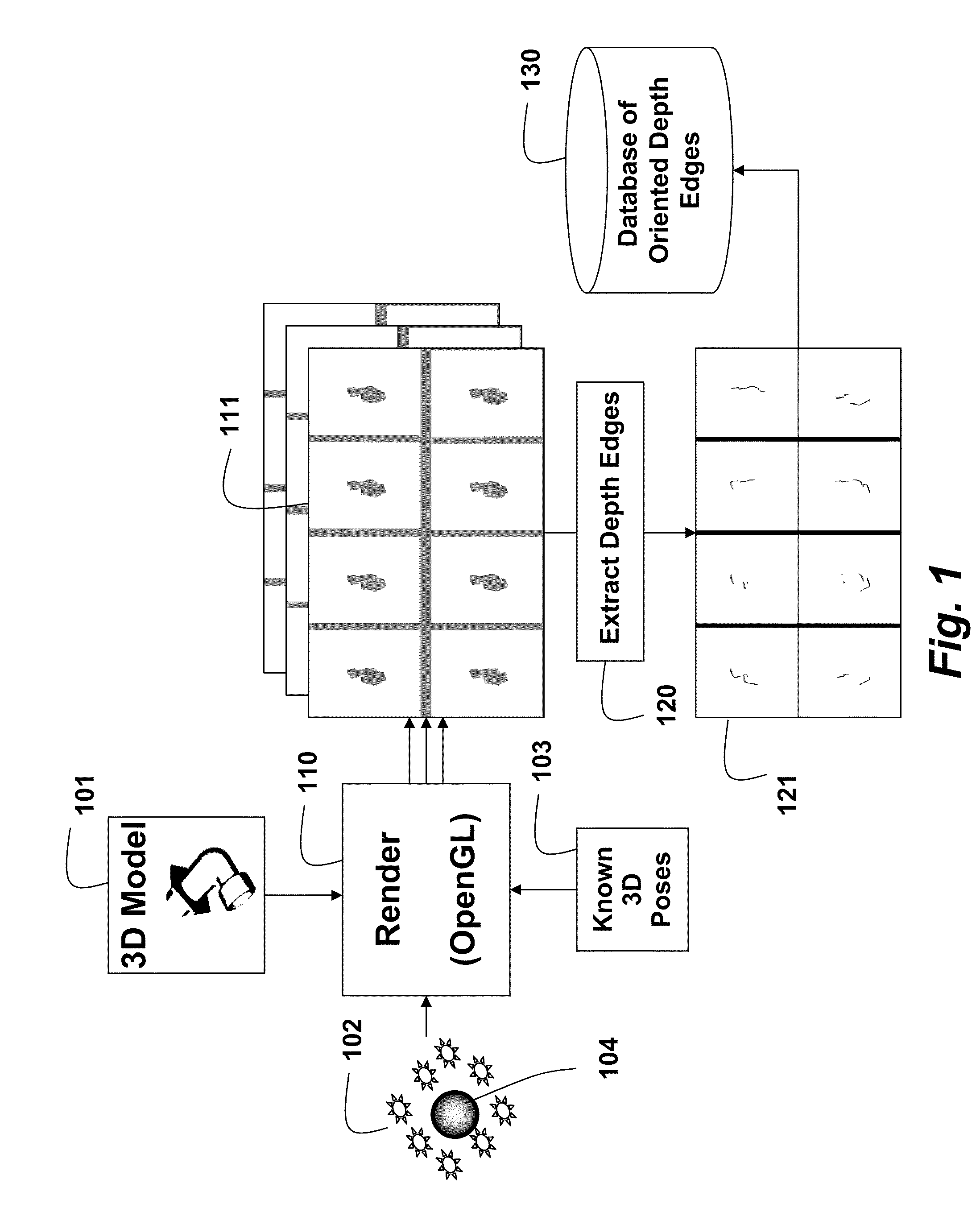
[0021]FIG. 1 show a pre-processing procedure for determining 3D poses of objects according to embodiments of our invention. The procedure can be performed in a processor including a memory, and input / output interfaces as known in the art. The pose includes the x, y, z translational location and the θ, φ, φ angular orientation. The method can be performed for various types of objects to construct a database used during actual operation of the method, also performed in a processor.

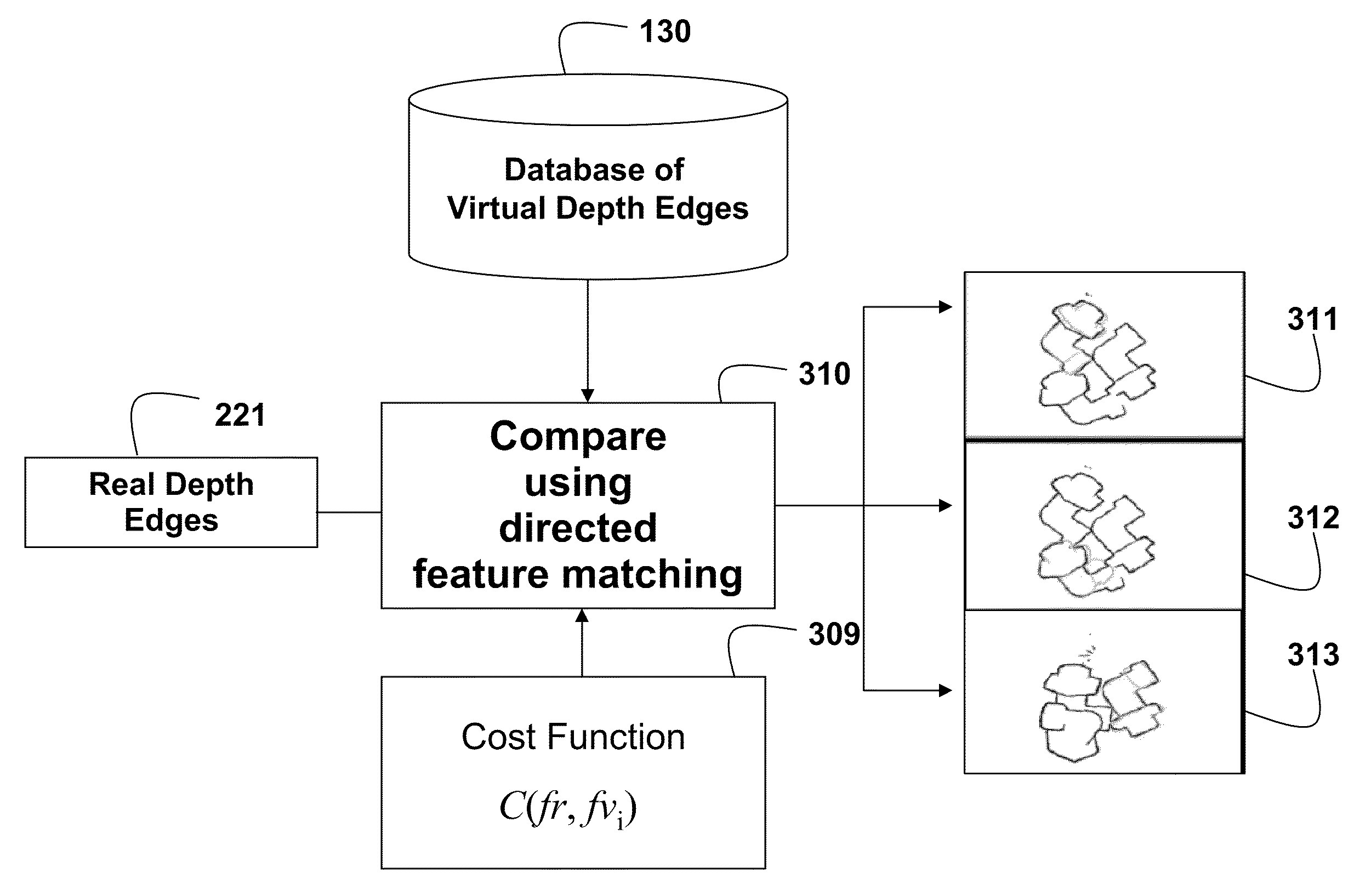
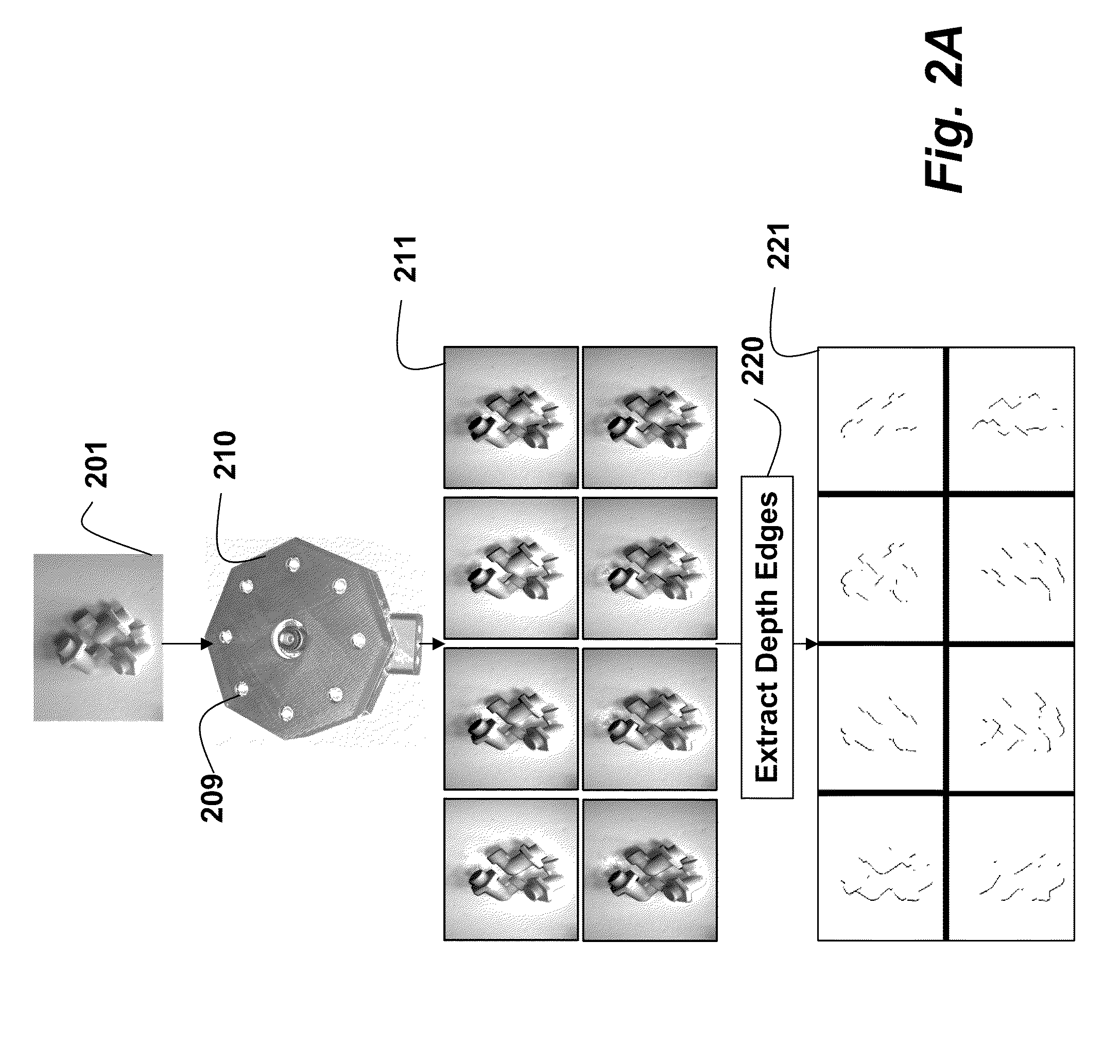
[0022]A rendering engine 110 (OpenGL) generates sets of virtual images 111 of a 3D model 101 of the object using a virtual camera. Each set is for a different possible known pose 101 of the model. The model is illuminated by a set of (eight) virtual point light sources 102 arranged around a lens 104 of the virtual camera. Therefore, there are eight virtual images in each set 111 for each known pose 103.

[0023]Virtual depth image edges 121 are constructed 120 from the set of virtual images as des...


PUM


Abstract

During pre-processing, a 3D model of the object is rendered for various poses by arranging virtual point light sources around the lens of a virtual camera. The shadows are used to obtain oriented depth edges of the object illuminated from multiple directions. The oriented depth edges are stored in a database. A camera acquires images of the scene by casting shadows onto the scene from different directions. The scene can include one or more objects arranged in arbitrary poses with respect to each other. The poses of the objects are determined by comparing the oriented depth edges obtained from the acquired images to the oriented depth edges stored in the database. The comparing evaluates, at each pixel, a cost function based on chamfer matching, which can be speed up using downhill simplex optimization.

Description

FIELD OF THE INVENTION[0001]This invention relates generally to computer vision systems, and more particularly to systems for determining the pose of objects for robotic picking applications.BACKGROUND OF THE INVENTION[0002]Industrial robots repeat the same task with high accuracy and precision. In some industrial applications, such as manufacturing and assembly, robots pick parts (objects), and place the objects for subsequent processing. The robots require the pose of the objects. Any deviations can result in suboptimal performance, or even damage to the robotic arm or object.[0003]Typically, custom designed mechanical and electro-mechanical systems are used to pick the objects with a known pose. In some applications, the objects are first sorted manually to facilitate the picking by the robot.[0004]Robots can use computer vision techniques to determine the pose of the objects before the objects are picked. However, deployment of computer vision enabled robots continues to be limi...

Claims


Application Information

Patent Timeline
Patent Type & Authority Applications(United States)
IPC IPC(8): G06K9/62G06K9/46
CPCG06T2207/30164G06T7/0044G06T7/74
Inventor AGRAWAL, AMIT K.WU, CHANGHUARASKAR, RAMESH N.THORNTON, JAY
Owner MITSUBISHI ELECTRIC RES LAB INC
Why Eureka
Try Eureka