Acoustic respiratory monitoring systems and methods

a technology of respiratory monitoring and monitoring system, applied in the field of acoustic respiratory monitoring system and method, can solve the problems of loss of sound content, reduction of substantial out-of-phase noise components of the plurality of signals, so as to improve the overall dynamic range of the sensor, high input dynamic range, and high output dynamic range

Active Publication Date: 2011-05-26
JPMORGAN CHASE BANK NA
View PDF52 Cites 357 Cited by
  • Summary
  • Abstract
  • Description
  • Claims
  • Application Information

AI Technical Summary

Benefits of technology

[0013]To achieve these and other benefits, componentry in the sensor data path generally compresses, reduces, or otherwise modifies a signal output by a sensing element or other component, improving the overall dynamic range of the sensor. For example, a piezoelectric film or other sensing element may have a relatively high input dynamic range, and may therefore be capable of generating a signal representing a wide range of sound intensity values. The sensing element may also have a relatively high output dynamic range and thus have a large range of possible output signal values (e.g., voltage values). However, one or more subsequent components in the sensor data path, such as a preamplifier or other circuit, may have a relatively lower input dynamic range, and thus be capable of processing a range of input signal values that is significantly smaller than the range of values produced by the sensing element.
[0014]If the unmodified signal from the sensing element is provided to the preamplifier, the preamplifier m...

Problems solved by technology

This can result in a loss of sound content, and a corresponding reduction in the overall dynamic range of the sensor.
Moreover, the noi...

Method used


Image

  • Acoustic respiratory monitoring systems and methods
  • Acoustic respiratory monitoring systems and methods
  • Acoustic respiratory monitoring systems and methods

Examples


Embodiment Construction

[0042]Various embodiments will be described hereinafter with reference to the accompanying drawings. These embodiments are illustrated and described by example only, and are not intended to be limiting.

System Overview

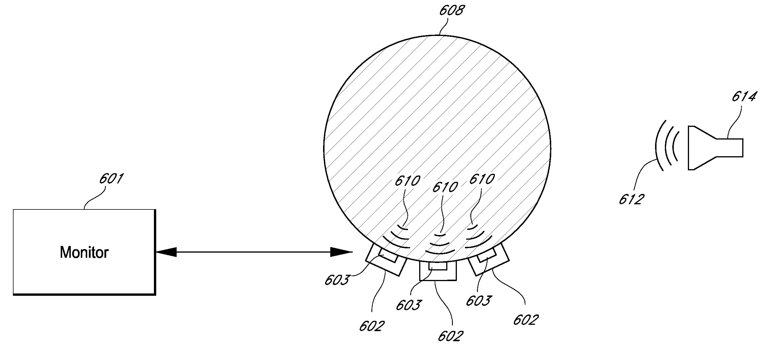
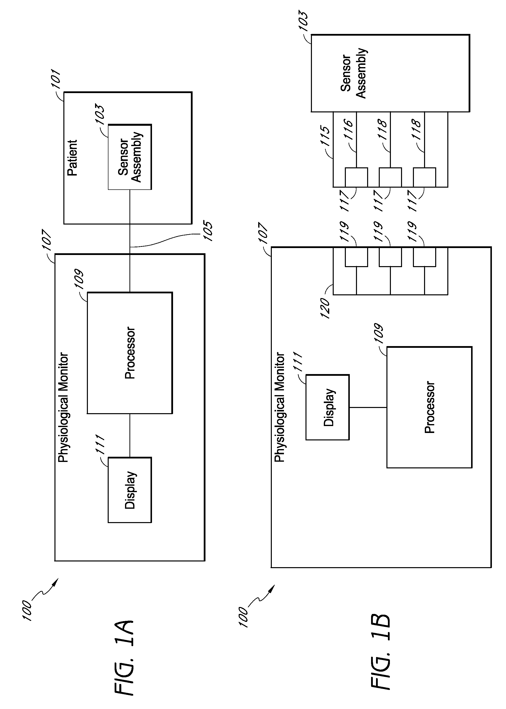
[0043]In various embodiments, an acoustic sensor configured to operate with a physiological monitoring system includes an acoustic signal processing system that measures and / or determines any of a variety of physiological parameters of a medical patient. For example, in one embodiment, the physiological monitoring system includes an acoustic monitor. The acoustic monitor may be an acoustic respiratory monitor which can determine any of a variety of respiratory parameters of a patient, including respiratory rate, expiratory flow, tidal volume, minute volume, apnea duration, breath sounds, riles, rhonchi, stridor, and changes in breath sounds such as decreased volume or change in airflow. In addition, in some cases the acoustic signal processing system monitors other phys...


PUM


Abstract

An acoustic sensor is provided according to certain aspects for non-invasively detecting physiological acoustic vibrations indicative of one or more physiological parameters of a medical patient. The sensor can include an acoustic sensing element configured to generate a first signal in response to acoustic vibrations from a medical patient. The sensor can also include front-end circuitry configured to receive an input signal that is based at least in part on the first signal and to produce an amplified signal in response to the input signal. In some embodiments, the sensor further includes a compression module in communication with the front-end circuitry and configured to compress portions of at least one of the input signal and the amplified signal according to a first compression scheme, the compressed portions corresponding to portions of the first signal having a magnitude greater than a predetermined threshold level.

Description

CROSS-REFERENCE TO RELATED APPLICATIONS[0001]This application claims the benefit of priority under 35 U.S.C. §119(e) of U.S. Provisional Application No. 61 / 252,099, filed Oct. 15, 2009, the disclosure of which is incorporated in its entirety by reference herein.[0002]Additionally, this application relates to the following U.S. patent applications, the disclosures of which are incorporated in their entirety by reference herein:App. No.Filing DateTitleAttorney Docket60 / 893853Mar. 08, 2007MULTI-PARAMETERMCAN.014PRPHYSIOLOGICAL MONITOR60 / 893850Mar. 08, 2007BACKWARD COMPATIBLEMCAN.015PRPHYSIOLOGICAL SENSOR WITHINFORMATION ELEMENT60 / 893858Mar. 08, 2007MULTI-PARAMETER SENSOR FORMCAN.016PRPHYSIOLOGICAL MONITORING60 / 893856Mar. 08, 2007PHYSIOLOGICAL MONITOR WITHMCAN.017PRFAST GAIN ADJUST DATAACQUISITION12 / 044883Mar. 08, 2008SYSTEMS AND METHODS FORMCAN.014ADETERMINING A PHYSIOLOGICALCONDITION USING AN ACOUSTICMONITOR61 / 252083Oct. 15, 2009DISPLAYING PHYSIOLOGICALMCAN.019PRINFORMATION## / ######Oc...

Claims


Application Information

Patent Timeline
IPC IPC(8): A61B7/00
CPCA61B7/003
Inventor TELFORT, VALERY G.WYLIE, MARK
Owner JPMORGAN CHASE BANK NA
Why Eureka
Try Eureka