Composite gas fluid flow measuring method and its device

a gas fluid flow and measuring method technology, applied in the direction of instruments, heat measurement, volume metering, etc., can solve the problems of high manufacturing cost, complex structure, and difficulty in a single device for measuring gas fluid flow, and achieve low measurement accuracy, low applicability of conventional devices, and narrow measurement range.

Inactive Publication Date: 2011-05-26
MEMSIC
View PDF6 Cites 19 Cited by
  • Summary
  • Abstract
  • Description
  • Claims
  • Application Information

AI Technical Summary

Benefits of technology

[0003]Accordingly, the present invention is directed to a composite method and device for measuring gas fluid flow with a wide measurement range and high applicability, so as to solve the problem of narrow measurement range and low applicability of the conventional device for measuring gas fluid flow.
[0004]The present invention is also directed to a composite method and device for measuring gas fluid flow with high measurement accuracy and superior reliability, so as to solve the problem of low measurement accuracy and poor reliability of the conventional device for measuring gas fluid flow.
[0005]To achieve the above technical objectives, the present invention adopts the following technical solutions. A composite method for measuring gas fluid flow includes providing a bypass pipe astride a mechanical device for measuring gas fluid flow with a temperature sensor and a pressure sensor, in which an MEMS flowrate sensor is provided on the bypass pipe, the temperature sensor, the pressure sensor, the mechanical device for measuring gas fluid flow and the MEMS flowrate sensor are all connected to a data processing system linked with a data display system, measured data from the temperature sensor, the pressure sensor, the mechanical device for measuring gas fluid flow and the MEMS flowrate sensor is processed by the data processing system and gas fluid flow data is displayed by the data display system. A bypass pipe is provided astride a mechanical device for measuring gas fluid flow, an MEMS flowrate sensor is provided on the bypass pipe, measured data from the two flowrate measurement devices is processed by a data processing system, and finally gas fluid flow data is displayed by a data display system, so that through the combination of the mechanical device for measuring gas fluid flow that has high stability and accuracy for a large flowrate with the MEMS flowrate sensor that is distinctly advantageous in measurement of a small flowrate, not only the measurement range and the applicability of the device for measuring gas fluid flow are effectively expanded, but also the measured data from the two measurement devices is considered in the data processing process of the data processing system, thereby improving the measurement accuracy of the gas fluid flow. Moreover, as the two measurement devices operate at the same time, the reliability of the entire device for measuring gas fluid flow is greatly improved.

Problems solved by technology

However, each type of these devices has its own limitations.
For example, a mechanical device for measuring gas fluid flow has a stable performance and high measurement accuracy when the gas fluid flow is large, but introduces a large error when the gas fluid flow is small, for example, a vortex street device for measuring gas fluid flow can hardly perform accurate measurement when the gas fluid flow is smaller than 5 m / s; while a thermal device for measuring gas fluid flow is suitable for measurement of a small gas fluid flow, but introduces a large error when the gas fluid flow is large.
Therefore, it is difficult for a single device for measuring gas fluid flow to achieve a wide-range and high-accuracy measurement.
Although the above device expands the measurement range and improves the measurement accuracy to a certain degree, the device has a complex structure and high manufacturing cost, and meanwhile, it is also difficult to eliminate the influence of flow pattern variation in practical applications of the device.

Method used


Image

  • Composite gas fluid flow measuring method and its device
  • Composite gas fluid flow measuring method and its device
  • Composite gas fluid flow measuring method and its device

Examples


embodiment 1

Preferred Embodiment 1

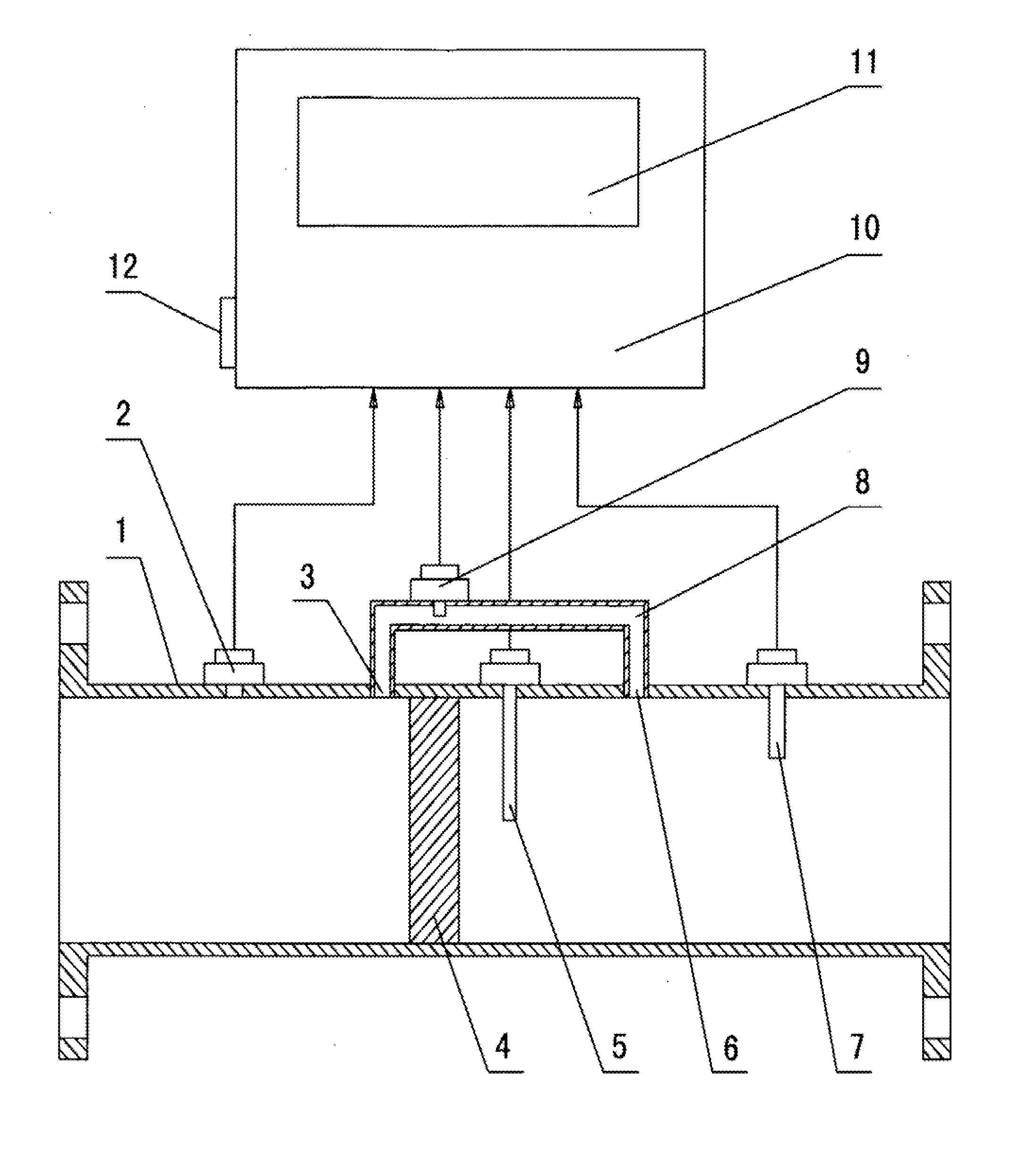
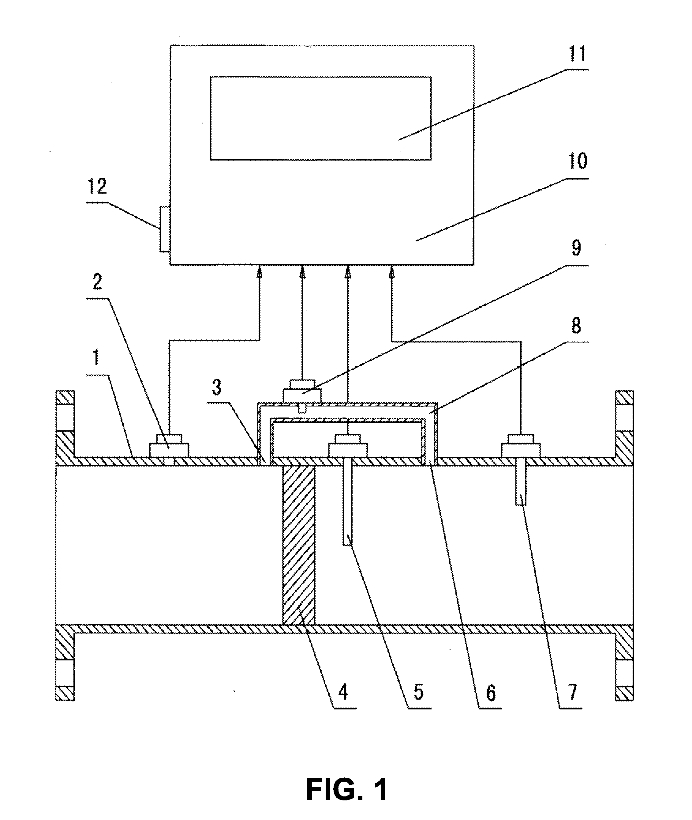
[0018]A composite method for measuring gas fluid flow of a preferred Embodiment includes providing a bypass pipe astride a mechanical device for measuring gas fluid flow with a temperature sensor and a pressure sensor, in which an MEMS flowrate sensor is provided on the bypass pipe, wherein the temperature sensor, the pressure sensor, the mechanical device for measuring gas fluid flow and the MEMS flowrate sensor are all connected to a data processing system linked to a data display system, and the measured data from the temperature sensor, the pressure sensor, the mechanical device for measuring gas fluid flow and the MEMS flowrate sensor is processed by the data processing system and gas fluid flow data is displayed by the data display system. The data processing system collectively analyzes the measured data from the mechanical device for measuring gas fluid flow after temperature and pressure compensation and the data from the MEMS flowrate sensor, uses the...

embodiment 2

Preferred Embodiment 2

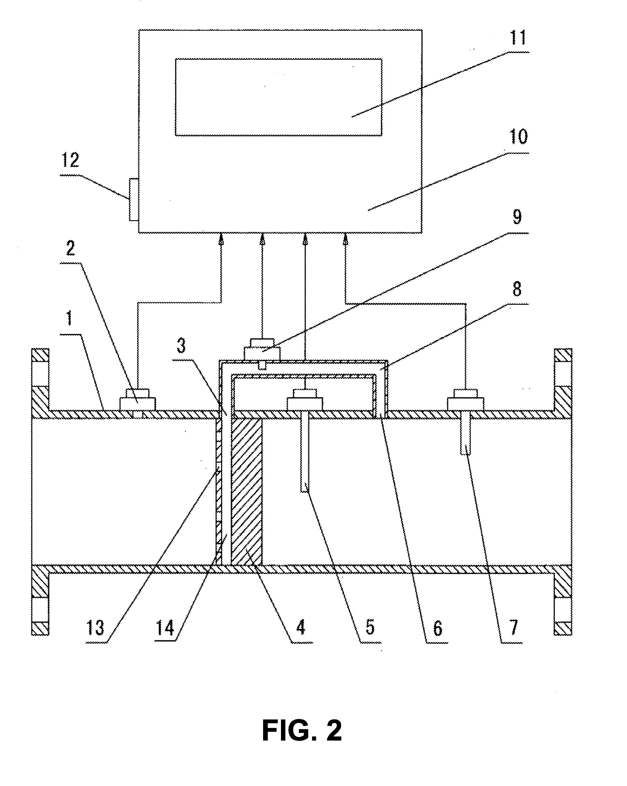
[0020]A preferred Embodiment 2 adopts such a measurement method that when the mechanical device for measuring gas fluid flow or the MEMS flowrate sensor has no measured data, the data processing system determines final gas fluid flow data according to the remaining measured data and based on a preset weighting curve, and the other methods are the same as Embodiment 1.

[0021]A composite device for measuring gas fluid flow of preferred Embodiment 2 is shown in FIG. 2. The composite device for measuring gas fluid flow includes a bypass pipe 8 astride a vortex street device for measuring gas fluid flow with a temperature sensor 7 and a pressure sensor 2 on a meter body 1. An averaging pitot tube 14 and pressure taps 13 are disposed on a vortex generator 4 according to position requirements of total pressure taps of an averaging pitot tube, an outlet end of the averaging pitot tube 14 is connected to an inlet 3 of the bypass pipe 8, and an outlet 6 of the bypass pipe...


PUM


Abstract

A composite method for measuring gas fluid flow, comprising the steps of: (a) providing a bypass pipe astride to a mechanical device for measuring gas fluid flow with a temperature sensor and a pressure sensor, (b) providing an MEMS flowrate sensor on the bypass pipe, (c) connecting the temperature sensor, the pressure sensor, the mechanical device for measuring gas fluid flow and the MEMS flowrate sensor to a data processing system, and (d) linking the data processing system with a data display system, wherein the measured data from the temperature sensor, the pressure sensor, the mechanical device for measuring gas fluid flow and the MEMS flowrate sensor is processed by the data processing system and gas fluid flow data is displayed by the data display system.

Description

FIELD OF THE INVENTION[0001]The present invention relates to the field of gas fluid flow measurement, and more particularly to a composite gas fluid flow measuring method and device with a wide measurement range, high measurement accuracy and superior reliability.BACKGROUND OF THE INVENTION[0002]It is well known that currently, many methods may be used for measuring gas fluid flow, and corresponding test devices are also diverse. However, each type of these devices has its own limitations. For example, a mechanical device for measuring gas fluid flow has a stable performance and high measurement accuracy when the gas fluid flow is large, but introduces a large error when the gas fluid flow is small, for example, a vortex street device for measuring gas fluid flow can hardly perform accurate measurement when the gas fluid flow is smaller than 5 m / s; while a thermal device for measuring gas fluid flow is suitable for measurement of a small gas fluid flow, but introduces a large error ...

Claims


Application Information

Patent Timeline
Patent Type & Authority Applications(United States)
IPC IPC(8): G01F1/34G06F19/00
CPCG01F1/32G01F1/3254G01F15/024G01F1/6845G01F1/46G01F1/3259
Inventor HAN, HUAICHENGMAO, JULIN
Owner MEMSIC
Why Eureka
Try Eureka