Supercharge Your Innovation With Domain-Expert AI Agents!

Plastic Pallet

a technology of plastic pallets and racks, applied in the field of plastic racks, can solve the problems of high cost of materials, high operating costs of industries, and the production of this type of pallets, and achieve the effect of great resistance to impacts

Active Publication Date: 2011-06-02
PLASTICOS TECNICOS MEXICANOS S A DE
View PDF43 Cites 16 Cited by
  • Summary
  • Abstract
  • Description
  • Claims
  • Application Information

AI Technical Summary

Benefits of technology

[0014]Another object of the present invention is to provide a plastic pallet that can be wholly recyclable.
[0015]A further object of the present invention is to provide a pallet having anti-slipping edges that also are useful to bear side impacts.
[0018]The base structure includes at least four peripheral posts and a central post; there being provided said deck structure with posts corresponding to each of the base posts, so that, in a coupled position, each of the base posts can be coupled to the deck post correspondingly positioned, thus forming said peripheral and central columns. Additionally, when said base structure is coupled to said deck structure, in every peripheral column and central column will be provided an outer wall and an inner wall, separated apart by a space wherein a foamed thermoplastic material packing is introduced, selected from the group of polyolefins including low-density polyethylene (LDPE), high-density polyethylene (HDPE), polypropylene (PP) and mixtures thereof. The function of the foamed material packing is to reinforce said columns, so as to increase the load capacity, as well as to absorb the impacts exerted on said plastic pallet during its everyday use, without a considerable increment in the total weight of said plastic pallet. Additionally, said foamed packing also provides a secure fastening of the unions between said posts forming said peripheral columns thus avoiding the motion due to the slack existing between said base and said deck, providing a greater fastening to one another, thus avoiding the disassembly of the pallet during the use thereof.
[0021]According to the principles of this invention, a pallet provides a suitable functioning of an automatic lift or a lift provided with manual skid, whereby weights above 1700 Kg can be supported, loaded and moved, with a very intense traffic with the distribution and storage warehouses. It is to be considered that the maneuvers with the plastic pallet when loading commodities into the trucks is carried out to a relatively high speed, whereby said plastic pallet is constantly impacted with the probes of said lifts. The design proposed herein diminishes the effect of said impacts on the integrity of the plastic pallet, thus increasing the useful life thereof and reducing the need for a frequent replacement. Likewise, at the upper part of said plastic pallet edges can be provided conferring a characteristic that prevents the sliding of the payload elements places onto said pallet during the transportation thereof.
[0022]Due to the operation conditions in the above referred to application, there is a great need of avoiding that the parts forming the body of the pallet become disassembled during the everyday use, further to increase the resistance to impacts provided by said lifts. This object is obtained in this invention, which provides a pallet with a body formed by at least two assembled and molded plastic structures forming a base and a deck, in such a manner that a space is provided within the columns, in which a foamed thermoplastic material packing is provided; wherein the material of the packing, as well as that of the base and of the deck, are selected from the polyolefins family (lo-density polyethylene, high-density polyethylene, propylene and mixtures thereof); preferable being the same material for every component, whereby, at the end of the useful life of the pallet,—that will be greater than that of the conventional pallets—, the pallet can be wholly recycled there being no necessary to carry out a materials separation.

Problems solved by technology

Therefore, the damages in the pallets are not only frequent, but an everyday problem and even more, a great amount of the damages result in the discarding of the pallets, whereby the replacement rate of said pallets is generally high, which to a certain measure influences the costs of operation of industries.
The invention disclosed in the Swistak document has the disadvantage of using thermosetting foamed materials, which does not provides for the recycling of said pallet in a whole, and, furthermore, the material thereof is of high cost.
The disadvantage of the product described by Moore et al is that the production of this type of pallet, when using a thermosetting polymer foam is consequently more expensive and has a greater production time; also, as it is known, this type of plastics are hardly recyclable.
Due to the characteristics described in said Moore patent document, the production of said pallet is considered highly expensive and with a high production time and, additionally, the type of material utilized is not considered as recyclable.
Said upper and lower docks, independently, have each characteristic connecting means to be coupled; this technique for the pallets having the disadvantage of the cost of said two separated apart molds.
Additionally, the impact to the platform during the use, such as, for example, of a forklift, can cause the side movement of the upper and lower decks, one relating another, resulting in the separation of said docks.
Said documents fail in pretending to obtain an anti-slipping surface due to the fact that, on the one side, said Nishitani document shows a gum layer attached and, on the other side, said pallet with anti-slipping surface described by Apps is a surface that must be brushed in order to obtain a rough zone which, in both cases and in a general manner, this object is hardly attained; and furthermore, they are not products resisting the impacts to be supported by said pallets daily.

Method used


Image

  • Plastic Pallet
  • Plastic Pallet
  • Plastic Pallet

Examples


Embodiment Construction

[0035]The present invention refers to an improved pallet or plastic rack molded from a thermoplastic material, preferably selected from the group of polyolefins including, among other, low-density polyethylene (LDPE), high-density polyethylene (HDPE), polypropylene (PP) and mixtures thereof.

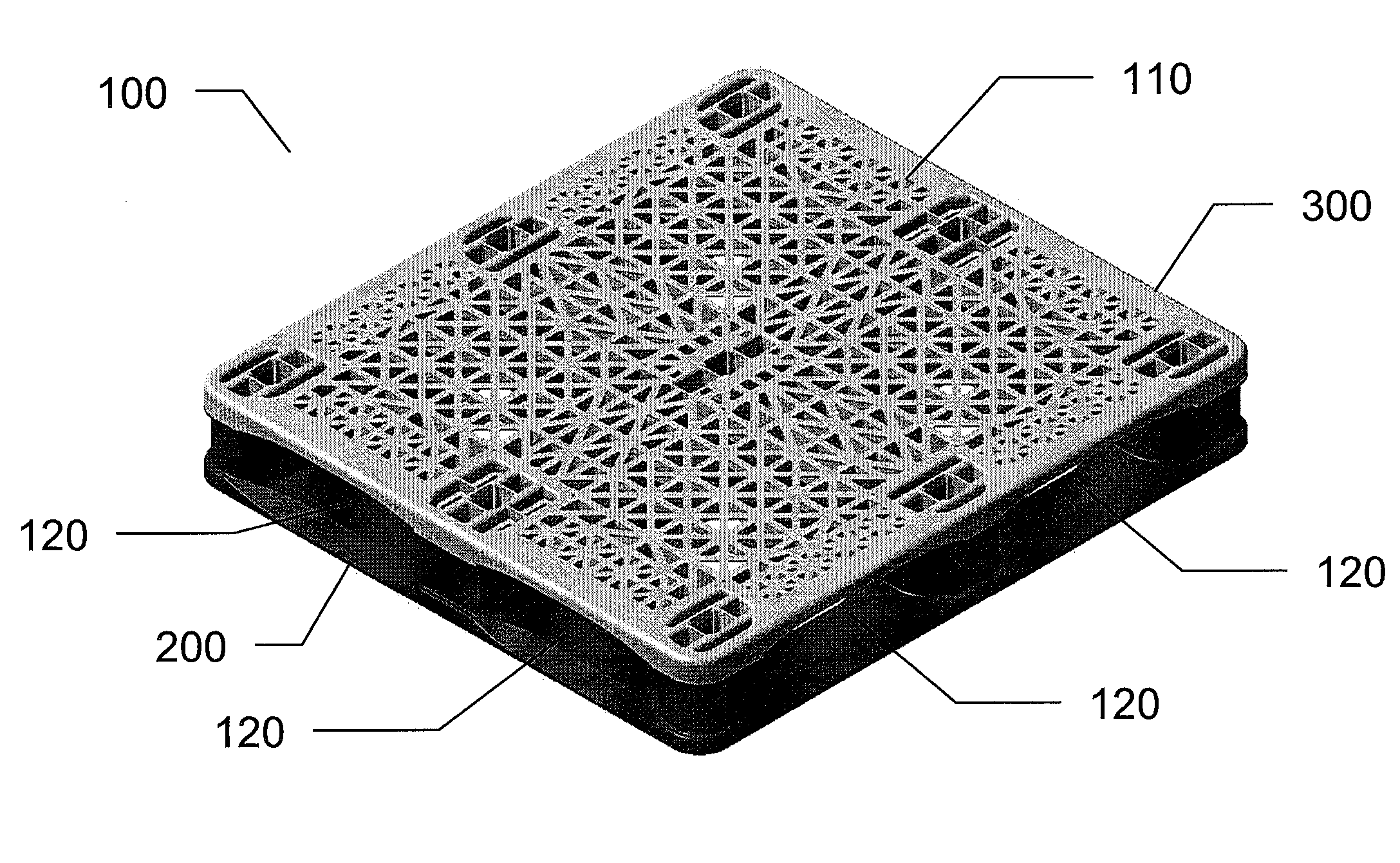
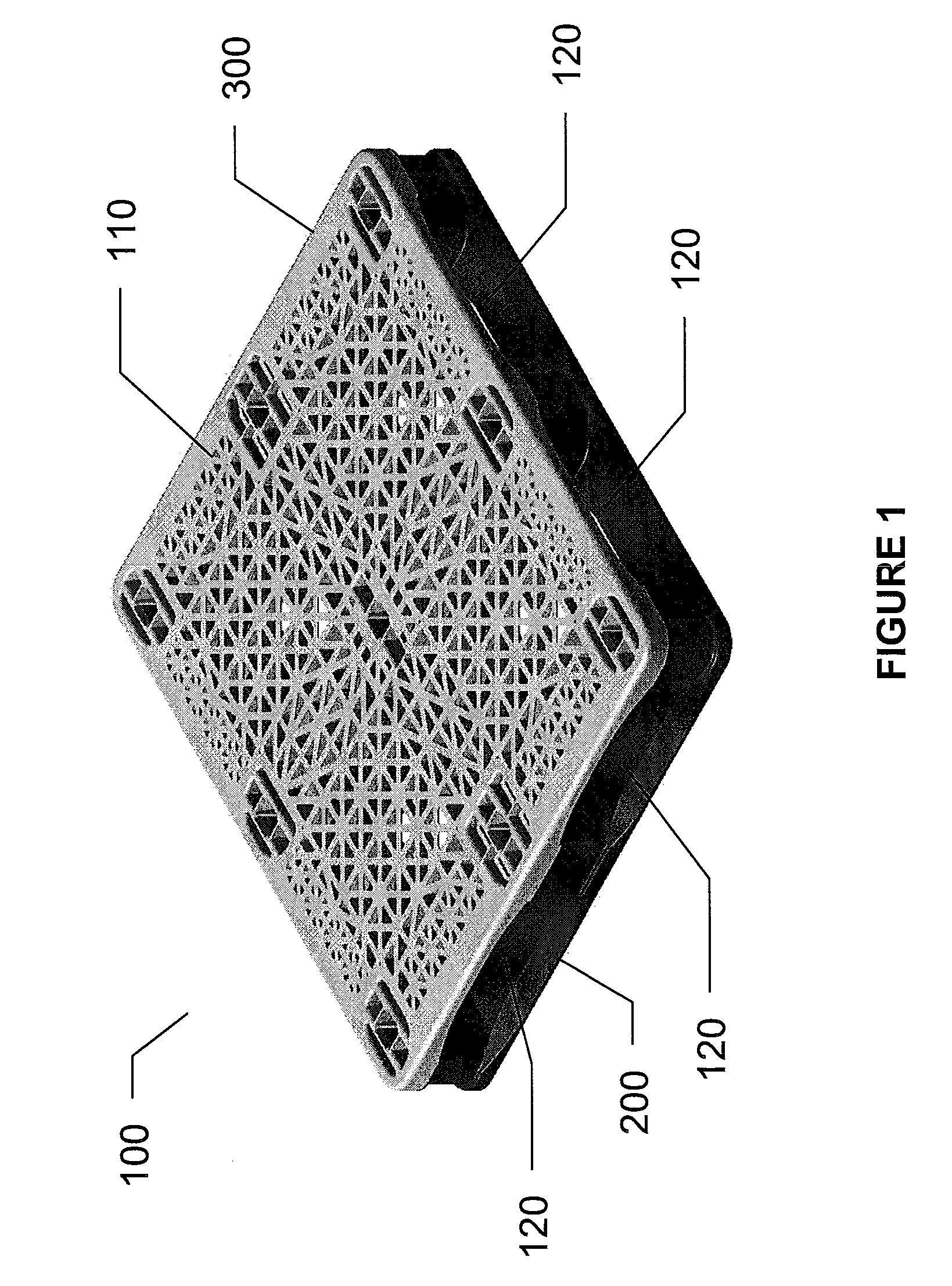
[0036]The body of the plastic pallet 100 of this invention, as shown in FIG. 1, is constituted by two molded structures forming a base 200 and a deck 300, assembled to one another in order to form a body 100 offering a surface 110 to support the object to be translated; said surface 110 offer preferably bores passing there through so as to provide for the draining of the liquids spilled on said surface, in order to clean and lighten the structure, and a plurality of side hollows 120 to provide for the passing of the freight “probes of the lift, for translating said plastic pallets and the objects deposited thereon. Preferably the corners of said pallet 100 of the invention are rounded.

[0037]Said ...


PUM


Abstract

This invention relates to an improved pallet formed from a thermoplastic material of the polyolefin type, from two pieces, base and deck, that can be coupled to each other with fastening means there between; said base and deck provided with posts projecting from each in a direction towards the other and that can be coupled to each other, in order to form hollow columns; wherein the posts projecting from the base form the outer wall of a plurality of columns, and the posts projecting from the deck are located at the interior of said columns, forming the inner wall thereof and thus constituting a hollow passage between said outer and inner walls of the columns; said hollow space is filled up with a foamed material to provide a greater impact resistance and resistance to the disassembling under normal conditions of operation. The employment of the same material to form the pieces to be coupled and the reinforcement packing provides that said pallet can be integrally recycled without the need to separate the components thereof due to the nature of the material.

Description

FIELD OF THE INVENTION[0001]This invention relates to plastic racks of the type employed for loading and transporting commodities, and specially relates to such racks also known as pallets.BACKGROUND OF THE INVENTION[0002]There is within the industrial premises high dynamics for loading, unloading and moving both inputs and outputs, which generally are piled onto plastic pallets to be moved by lifts. Said operations are generally carried out at a great speed, with the consequence of frequent impact of the pallets with the probes of said lifts and eventually said goods fall down from different heights. Therefore, the damages in the pallets are not only frequent, but an everyday problem and even more, a great amount of the damages result in the discarding of the pallets, whereby the replacement rate of said pallets is generally high, which to a certain measure influences the costs of operation of industries.[0003]Several attempts have been carried out in order to provide pallets more ...

Claims


Application Information

Patent Timeline
IPC IPC(8): B65D19/38
CPCB65D19/0038B65D2519/00034B65D2519/00069B65D2519/00139B65D2519/00273B65D2519/00288B65D2519/00567B65D2519/00318B65D2519/00333B65D2519/00363B65D2519/00407B65D2519/00412B65D2519/00477B65D2519/00308
Inventor SOSA BRAVO, SERGIO
Owner PLASTICOS TECNICOS MEXICANOS S A DE
Features
  • R&D
  • Intellectual Property
  • Life Sciences
  • Materials
  • Tech Scout
  • Unparalleled Data Quality
  • Higher Quality Content
  • 60% Fewer Hallucinations
Learn More