

Cooling method and cooling system of electronic device
- Summary
- Abstract
- Description
- Claims
- Application Information
AI Technical Summary
Benefits of technology
Problems solved by technology
Method used
Image

Examples
embodiment
[1] Embodiment A
[0062]In an embodiment A, a cooling method and a cooling system of electronic devices capable of stably maintaining natural circulation of a cooling medium and preventing formation of dew on the surfaces of evaporators even when the cooling-medium flow rate of the evaporators is subjected to valve control in the cooling system of the cooling-medium natural-circulation method will be explained. Examples in which servers disposed in server rooms serve as electronic devices will be explained.
first embodiment
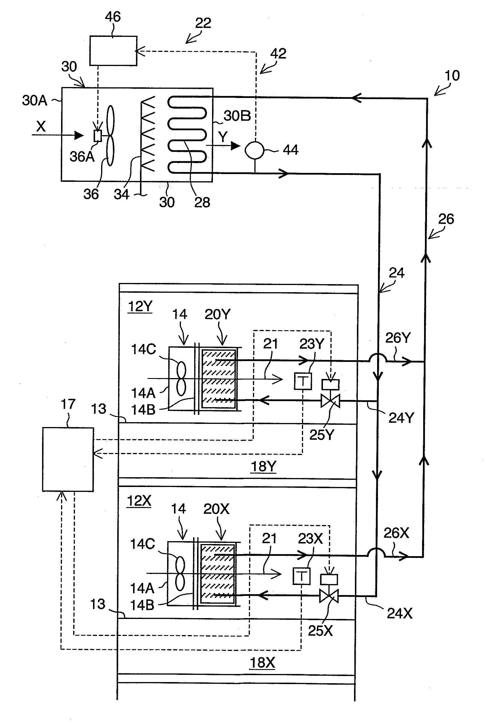
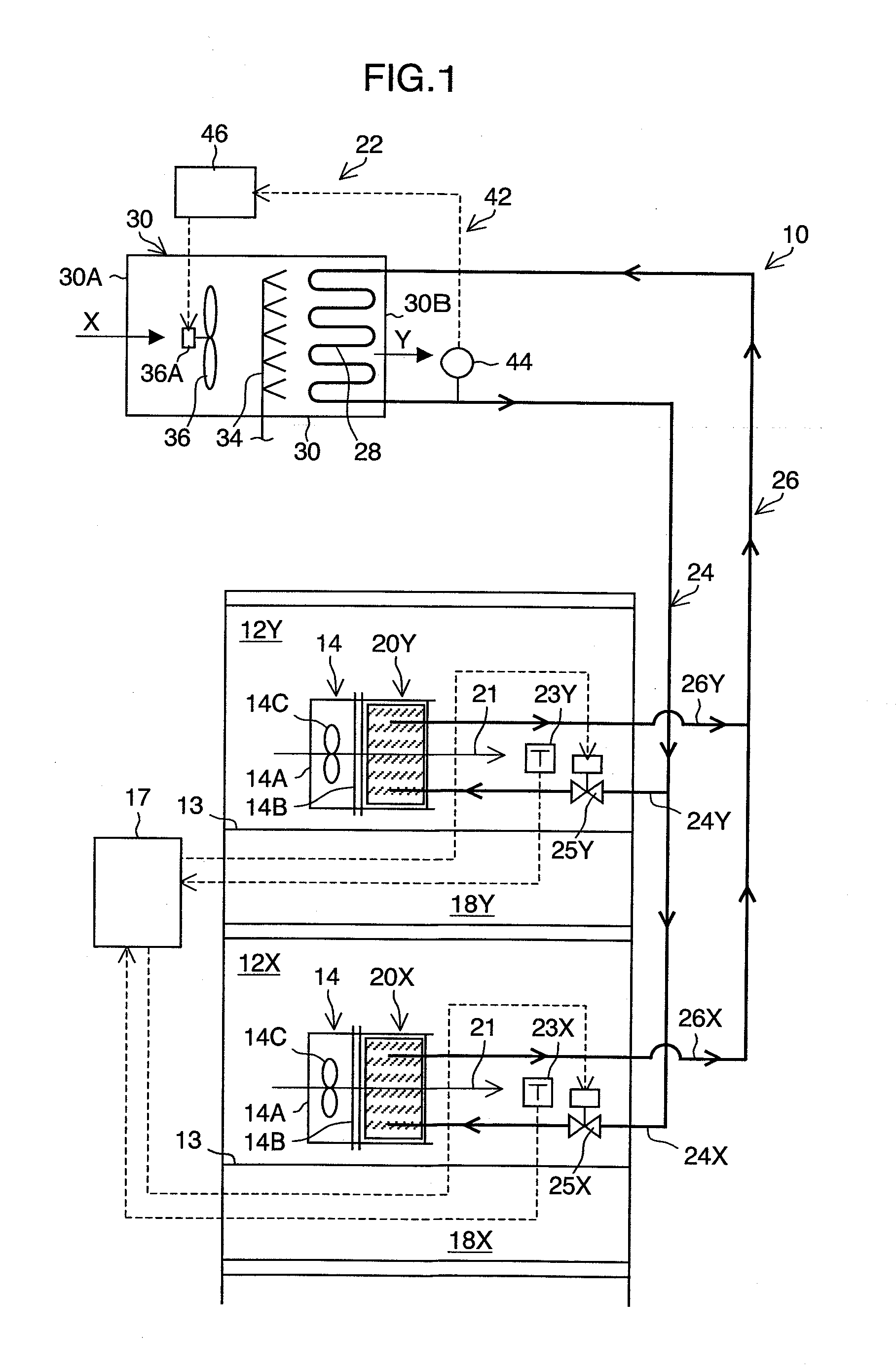
[0063]FIG. 1 is a schematic diagram showing the overall constitution of a first embodiment of a cooling system 10 of electronic devices.
[0064]The cooling system 10 shown in the diagram is a system, which locally cools the vicinities of servers 14 provided in server rooms 12X and 12Y in upper and lower two floors. Note that X appended to the reference numerals in the below description represents the members related to the cooling system of the lower floor, and Y represents the members related to the cooling system of the upper floor. In FIG. 1, one server 14 is shown in each of the server rooms 12X and 12Y; however, in practice, many servers 14 are disposed therein. Furthermore, usually, the servers 14 are installed in the server rooms 12X and 12Y in the manner in which the servers are stacked and housed in server racks (not shown).
[0065]Each of the servers 14 has a suction opening 14A and a discharge opening 14B for air and has a fan 14C in the interior thereof. When the fan 14C is ...
second embodiment
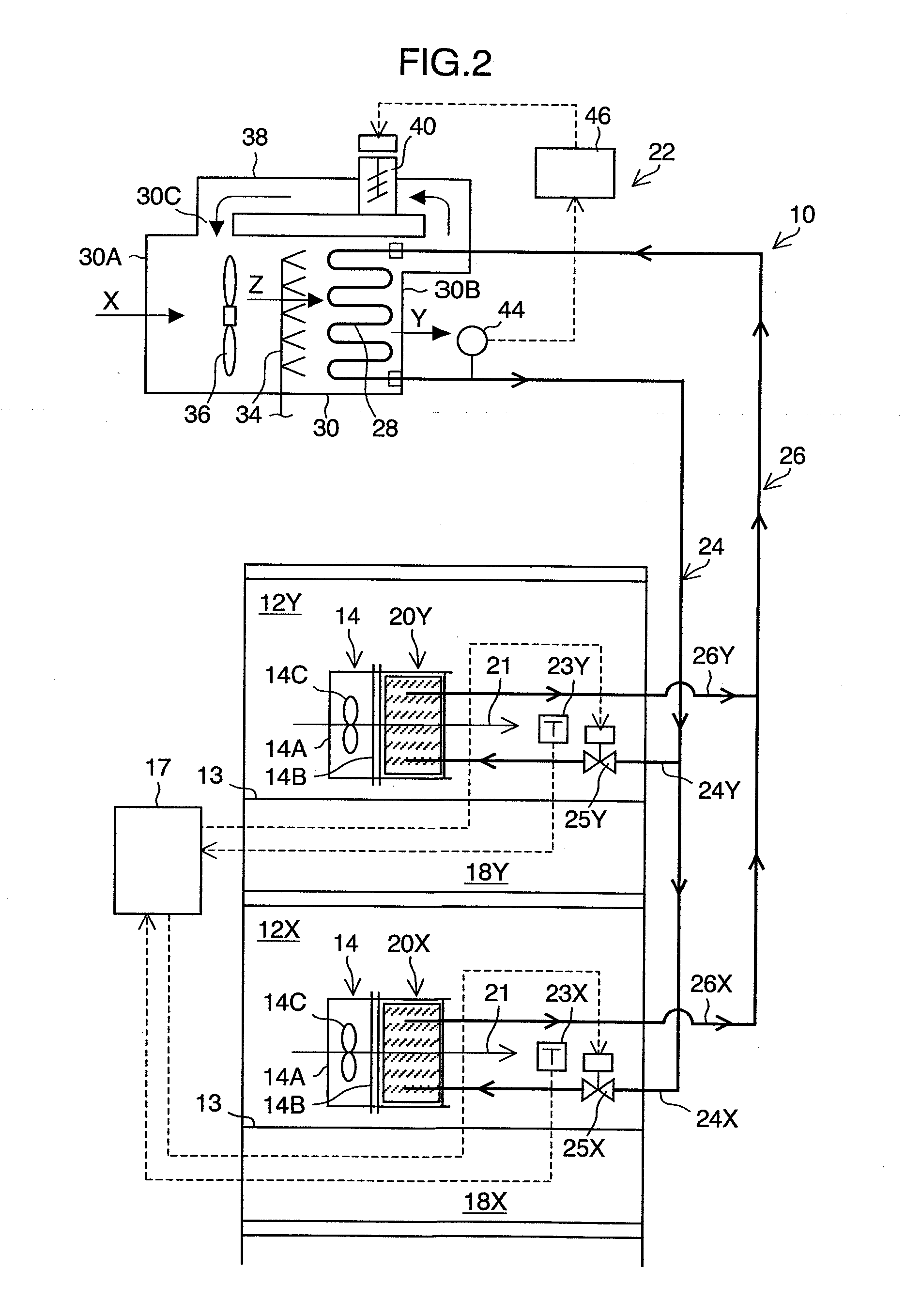
[0088]FIG. 2 is a schematic diagram showing the overall constitution of a second embodiment of the cooling system 10 of the electronic devices, which is a case in which a circulation duct type cooling tower is provided as a device which condenses the cooling-medium gas.
[0089]The parts common to those of the first embodiment are denoted by the same reference numerals, and explanations thereof will be omitted.
[0090]As shown in FIG. 2 and FIG. 3, a connecting hole 30C is bored in the intake opening 30A-side side surface of the cooling-tower main body 30, and part of the discharge opening 30B and the connecting hole 30C are mutually connected by a circulation duct 38. As a result, part of the temperature-increased discharge outside-air Y discharged from the discharge opening 30B is circulated to the vicinity of the intake opening 30A through the circulation duct 38; therefore, the discharge outside-air Y and the intake outside-air X is mixed with each other. As a result, the outside air...
PUM
 Abstract
Description
Claims
Application Information