Vacuum bag for hot drape forming
- Summary
- Abstract
- Description
- Claims
- Application Information
AI Technical Summary
Benefits of technology
Problems solved by technology
Method used
Image

Examples
second embodiment
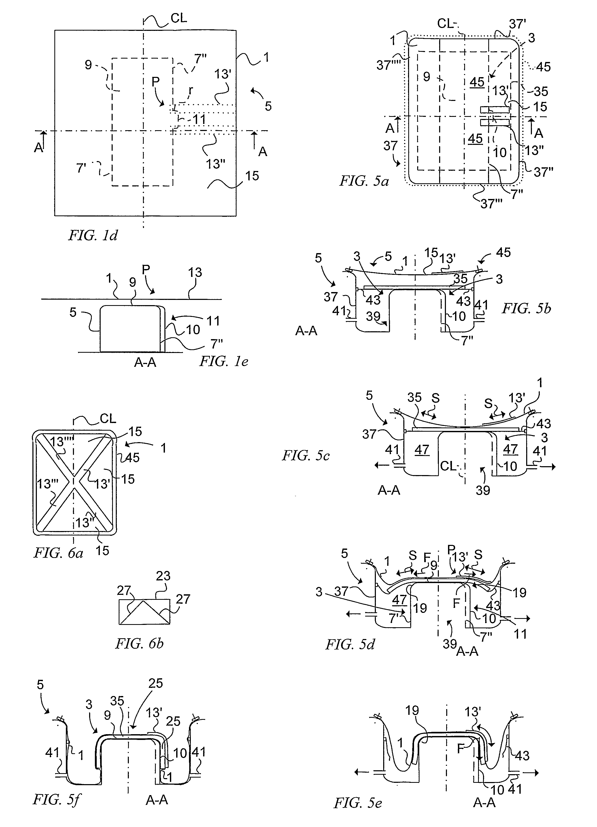
[0061]FIG. 1d schematically illustrates a second embodiment from above similar to that in FIG. 1a, but wherein the elongated bag section 13′, 13″ has a larger stiffness than surrounding bag sections 15 by integrating stiffening elements (not shown) into the bag 1 within the area of the elongated bag section 13′, 13″ during the manufacture of the bag 1. The bag 1 will have the same thickness over all the area of the bag 1 which is visible in FIG. 1e.
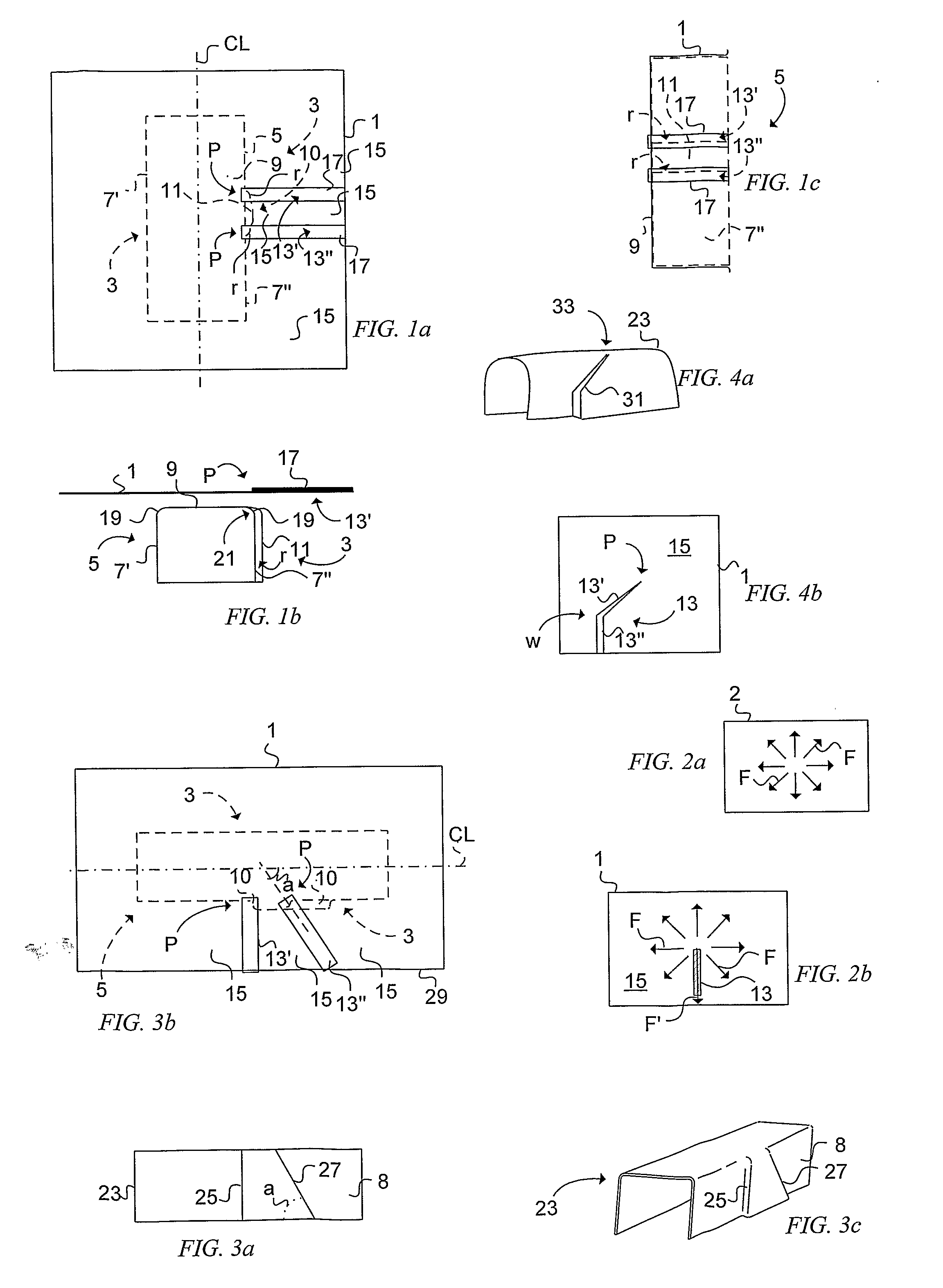
[0062]FIG. 2a schematically illustrates the principle for a bag 2 according to known technique. When the bag 2 is stretched by vacuum during the forming procedure, forming forces F are created which act on the blank to be formed. Since the bag 2 has a uniform stiffness, the forming forces F will be the same all over the area of the bag 2. FIG. 2b schematically illustrates the principle of the embodiments described above. The elongated bag section 13′ having a stiffness larger than surrounding bag sections 15 provides, when the bag 1 is s...
third embodiment
[0063]FIG. 3a schematically illustrates a composite article 23 being produced by a method according to a The article 23 comprises a vertical bevel 25 and an inclined bevel 27, both provided at a flange 8 of the article 23. See also FIG. 3c illustrating the article 23 in perspective. For forming the article 23 a bag 1 is provided with two elongated bag sections 13′, 13″, one of which 13′ is projecting from the centre line CL towards a long side 29 (see FIG. 3b) of the bag 1 and is perpendicular to the centre line CL. The other elongated bag section 13′ projects from the centre line CL with an inclined angle a corresponding with an angle of the inclined bevel 27 after fulfilled evacuation of the bag 1.
fourth embodiment
[0064]FIG. 4a schematically illustrates a composite article 23 formed by a method according to a The bevel 31 of the article 23 is angled, meaning that the forming tool 5 (not shown) comprises an elongated forming surface section being angled in a plane of the flange forming surface section. In FIG. 4b is shown a bag 1 (for forming the article 23 in FIG. 4a) comprising a stiffened elongated bag section 13 being angled at w. Since the end 33 (corresponding with the starting point P) of the bevel 31 of the has a relatively small area to be formed requiring a less forming force, the elongated bag section 13 at the position of the starting point P has a stiffness less than the stiffness of the remaining section of the elongated bag section 13 but larger than the surrounding bag sections 15 surrounding the elongated bag section 13. By arranging the elongated bag section 13 in such way the forming force quantity and the forming force direction can be controlled during the forming process...
PUM
| Property | Measurement | Unit |
|---|---|---|
| Force | aaaaa | aaaaa |
| Area | aaaaa | aaaaa |
| Stiffness | aaaaa | aaaaa |
Abstract
Description
Claims
Application Information
 - Generate Ideas
- Intellectual Property
- Life Sciences
- Materials
- Tech Scout
- Unparalleled Data Quality
- Higher Quality Content
- 60% Fewer Hallucinations
Browse by: Latest US Patents, China's latest patents, Technical Efficacy Thesaurus, Application Domain, Technology Topic, Popular Technical Reports.
© 2025 PatSnap. All rights reserved.Legal|Privacy policy|Modern Slavery Act Transparency Statement|Sitemap|About US| Contact US: help@patsnap.com