

Optical scan unit, image projector including the same, vehicle head-up display device, and mobile phone
a scanning unit and image technology, applied in the field of optical scanning units and image projectors including the same, can solve the problems of limited deflection angle of the optical deflector included in the mems device, projected images may have various kinds of deformation, and are not suitable for small-size electronic devices
- Summary
- Abstract
- Description
- Claims
- Application Information
AI Technical Summary
Benefits of technology
Problems solved by technology
Method used
Image

Examples
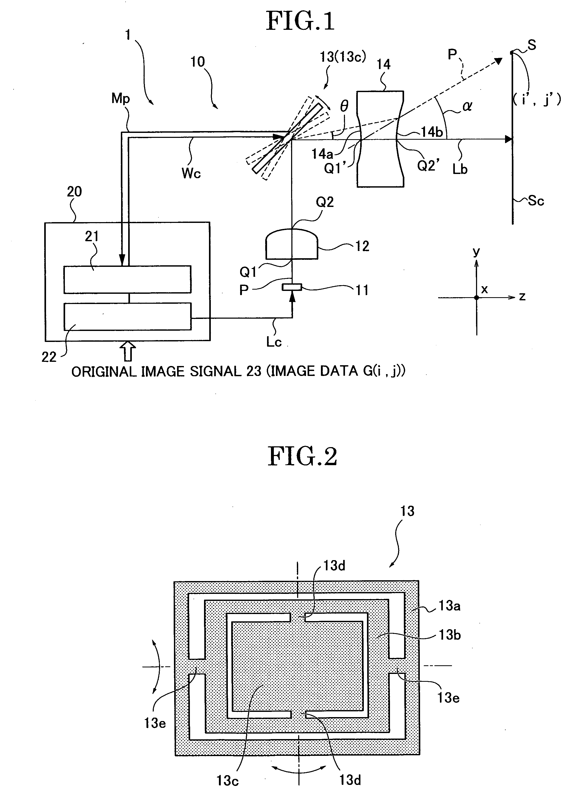
first embodiment
Modification of First Embodiment
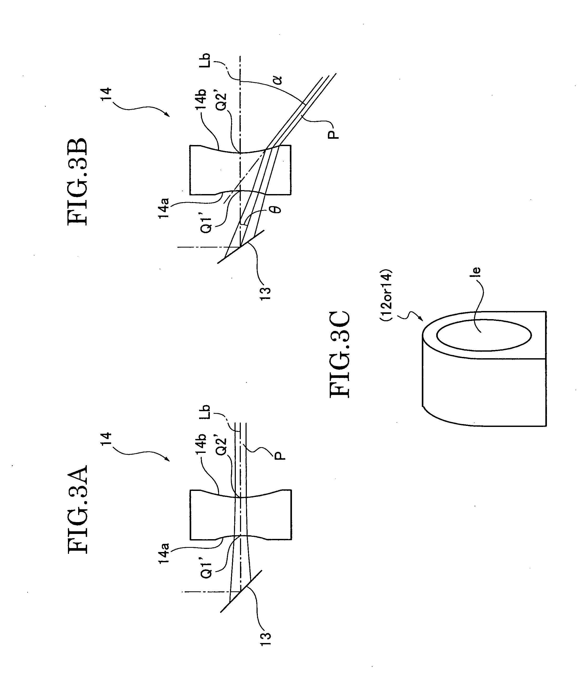
[0104]Next, a modification of the image projector according to the first embodiment is described. This modified embodiment uses an image projector 1t to find out through experiments how deformation of images on the screen Sc is changed in accordance with a change in the incidence angle φ of light on the mirror portion 13c. The structure of the image projector 1t is basically the same as that of the image projector 1 so that the same components and functions are given the same numeric codes as in the first embodiment, and a detailed description thereon is omitted. FIG. 14 schematically shows an optical scan unit 10t of the image projector 1t and optical paths at the incidence angle φ being 45 degrees.
[0105]Here, the incident optical axis Li refers to a traveling direction of a principal ray emitted from the light source 11 and transmitting through a divergent light conversion element 12t. The incidence angle φ refers to the angle of the incident optica...
second embodiment
Modification of Second Embodiment
[0128]Next, an image projector 1At (optical scan unit 10At) as a modification of the image projector 1A is described with reference to FIGS. 17 to 22. The image projector 1At (optical scan unit 10A) is another example of a color image projector in a smaller size. The structure thereof is basically the same as that of the image projector 1A in the second embodiment, so that the same functions and components are given the same numeric codes and a detailed description thereon is omitted. FIG. 17 schematically shows the structure of the image projector 1At but omits showing the control unit 20 for simplicity. FIG. 18 shows the cross section of a first divergent light conversion element 12At1 used in the image projector 1At, FIG. 19 shows the cross section of a second divergent light conversion element 12At2, FIG. 20 shows the cross section of an optical path combiner unit 16At, FIG. 21 shows the cross section of a focus lens 70, and FIG. 22 shows the cro...
third embodiment
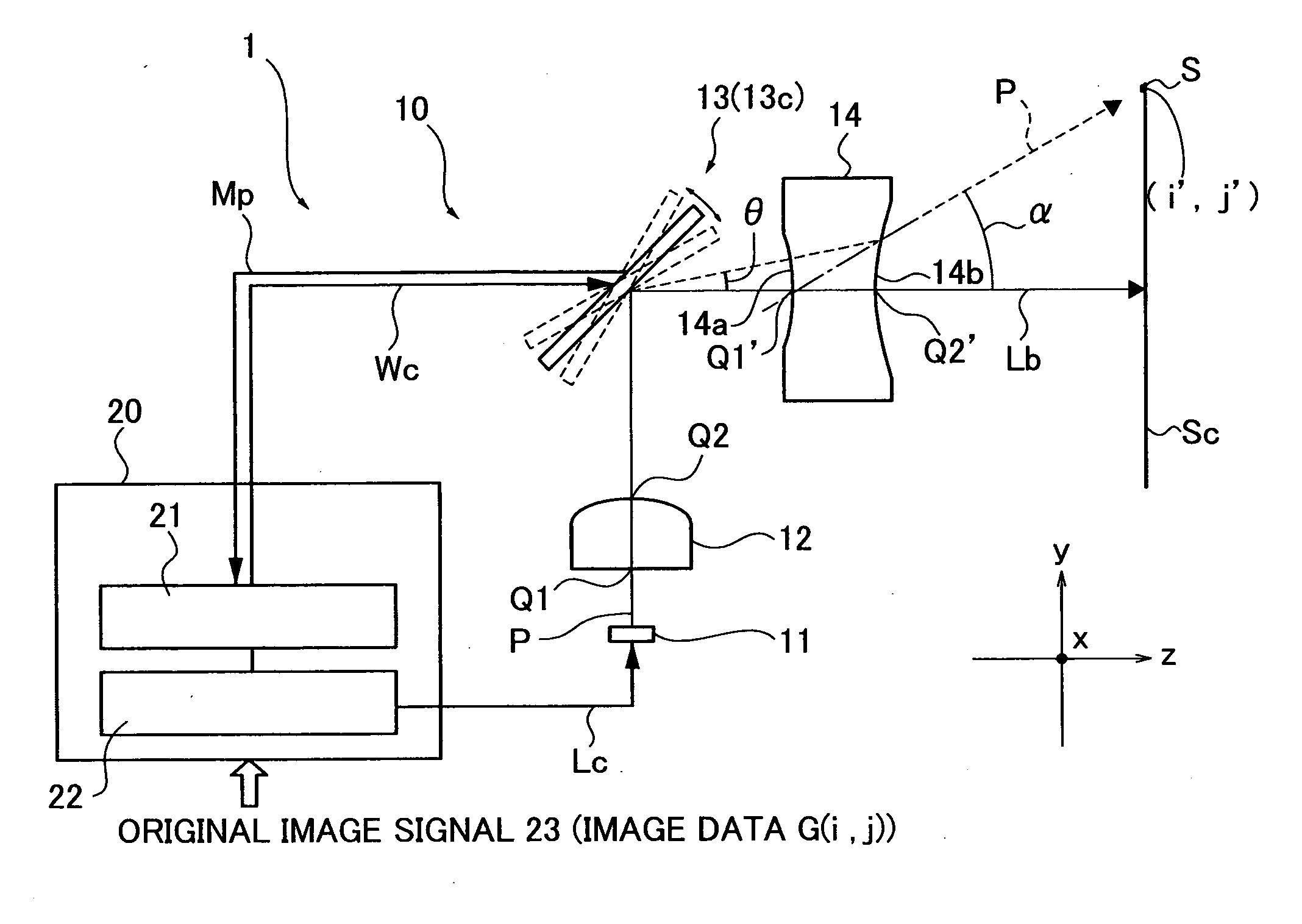
[0157]An image projector 1B according to the third embodiment is described with reference to FIG. 9. The image projector 1B comprises an additional function to form better color images than the image projector 1A according to the second embodiment. The structure of the image projector 1B is the same as that of the image projector 1A; therefore, the same functions and components thereof are given the same numeric codes and a detailed description thereon is omitted.
[0158]The image projector 1B includes a control unit 203 which includes an image processing unit 26 (image processing circuit) in addition to the optical deflector control unit 21 and the light emission amount control unit 22. In order to project a good image on the screen Sc, the image processing unit 26 corrects image data G (i, j) based on an original image signal 23 received by the control unit 203 and outputs the corrected image data G′ (i, j) to the optical deflector control unit 21 and the light emission amount contr...
PUM
 Abstract
Description
Claims
Application Information