Lithium-Ion Secondary Battery

a secondary battery and lithium-ion technology, applied in the direction of cell components, final product manufacturing, sustainable manufacturing/processing, etc., can solve the problems of poor heat-absorbing response, corrosion of the electrode terminal, and significant restrictions on the integration system constituted with a plurality of such batteries, and achieve the effect of high efficiency

Inactive Publication Date: 2011-06-02
HITACHI LTD
View PDF10 Cites 774 Cited by
  • Summary
  • Abstract
  • Description
  • Claims
  • Application Information

AI Technical Summary

Benefits of technology

[0012]In addition, while the structure with a cooling means for directly cooling the electric current path through which heat is also transmitted, assures a high level of cooling efficiency and superior battery volumetric efficiency, heat is dissipated only over a battery electrode terminal and thus, the structure requires forced cooling. In addition, as the electrode terminal is cooled directly, static electricity is generated, which, in turn, causes ready adhesion of suspended minute particulates, to lead to corrosion of the electrode terminal.
[0014]Accordingly, an object of the present invention is to provide a lithium-ion secondary battery that allows heat generated within the battery to be efficiently transmitted to the container so as to prevent deterioration of the battery characteristics attributable to high temperatures, without drastically altering the battery structure.
[0025]According to the present invention, heat generated inside the battery container be transferred to the battery container with high efficiency and thus, in the battery characteristics attributable to high temperatures can be effectively prevented without having to drastically alter the battery structure.

Problems solved by technology

In addition, an integrated system constituted with a plurality of such batteries may be subject to significant restrictions with regard to the positional arrangement with which the batteries may be disposed.
In addition, as the electrode terminal is cooled directly, static electricity is generated, which, in turn, causes ready adhesion of suspended minute particulates, to lead to corrosion of the electrode terminal.
However, the heat-absorbing response will become poor in an operating environment with significant output fluctuation or an operating environment where steep charge / discharge is repeated and thus, it may not be possible to keep the battery temperature at the desired level in such an operating environment.

Method used


Image

  • Lithium-Ion Secondary Battery
  • Lithium-Ion Secondary Battery
  • Lithium-Ion Secondary Battery

Examples


embodiment 1

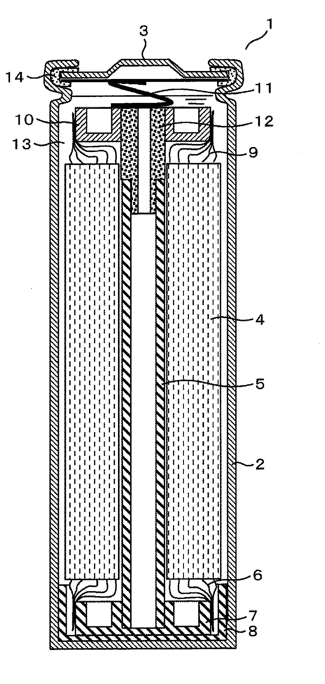
[0036]FIG. 1 is a schematic sectional view of the cylindrical lithium-ion secondary battery achieved in embodiment 1.

[0037]A lithium-ion secondary battery 1 in the embodiment includes a winding body 4 accommodated in the space formed by a steel-can (container) 2 and a top cap 3 and assumes a structure that allows heat generated at the winding body 4 during electrical charge / discharge to be dissipated to the outside by transmitting the heat to the steel-can 2.

[0038]It is to be noted that the winding body 4 is wrapped in a coil form around a cathode foil (cathode film) and an anode foil (anode film) via a porous separator that electrically separates them. In the cathode foil and the anode foil lithium ions can store and from the cathode foil and anode foil lithium ions can extract.

[0039]A center pin 5 is fitted at the center of the winding body 4, wound in a spiral form around the cathode electrode and the anode electrode, separated via the separator.

[0040]Numerous anode tabs 6 at the...

embodiment 2

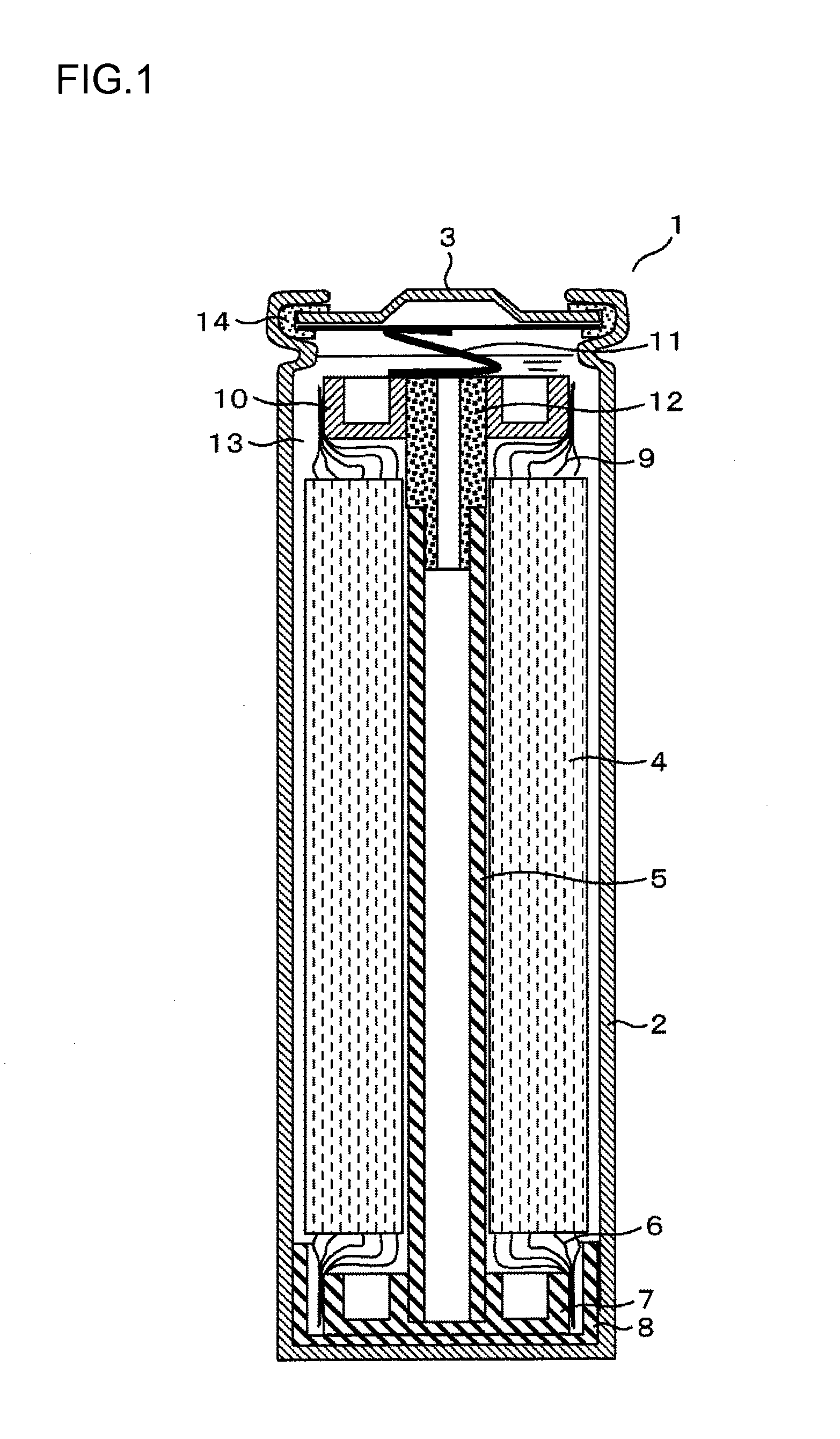
[0065]While the lithium-ion secondary battery according to the present invention is provided as a cylindrical lithium-ion secondary battery 1 in embodiment 1, the present invention is not limited to this battery shape and may be adopted in a prismatic battery or another polygonal battery as long as the battery includes a winding body.

[0066]In reference to FIGS. 2 and 3, the prismatic lithium-ion secondary battery achieved in embodiment 2 is described in detail. FIG. 2 is an external view of the prismatic lithium-ion secondary battery achieved in embodiment 2, whereas FIG. 3 is a sectional view of the prismatic lithium-ion secondary battery in FIG. 2 taken through line III-III.

[0067]The prismatic lithium-ion secondary battery in the embodiment includes a flat winding body 4 disposed with a lateral orientation, with the anode electrode located on the left side of the figures and the cathode electrode located on the right side of the figures.

[0068]The winding body 4 in the embodiment w...

embodiment 3

[0092]In reference to FIGS. 4 through 7, the prismatic lithium-ion secondary battery achieved in embodiment 3 is described. It is to be noted that the same reference numerals are assigned to parts identical to or equivalent to those in embodiment 2 and the following explanation focuses on the features distinguishing embodiment 3 from embodiment 2. The lithium-ion secondary battery achieved in embodiment 3 is ideal in automotive applications.

[0093]In the description of the lithium-ion secondary battery 1 achieved in embodiment 3, a battery container of box type 22 sealed with the top cap 3 as shown in FIG. 4 is referred to as a battery canister. The lithium-ion secondary battery 1 includes a center pin (center core) 5 formed as an integrated flat plate. As shown in FIG. 6, the center pin 5 is formed as an integrated unit that includes a center pin body 5a, a heat sink 8 connected to the center pin body 5a at an anode electrode-side end thereof and a connecting member 12B connected to...


PUM

PropertyMeasurementUnit
porosity rateaaaaaaaaaa
areaaaaaaaaaaa
electrically insulatingaaaaaaaaaa

Abstract

A lithium-ion secondary battery includes: a winding body in a coil formation at a battery container, the winding body wrapping a cathode film in which lithium ions store and from which lithium ions extract and a anode film in which lithium ions store and from which lithium ions extract, and the cathode film and the anode film being electrically separated from each other via a porous separator; and a heat sink disposed inside the battery container, which contacts the battery container and transmits heat inside the winding body to the battery container.

Description

INCORPORATION BY REFERENCE[0001]The disclosure of the following priority application is herein incorporated by reference:Japanese Patent Application No. 2009-270962 filed Nov. 30, 2009BACKGROUND OF THE INVENTION[0002]1. Field of the Invention[0003]The present invention relates to a lithium-ion secondary battery, and more specifically, it relates to a lithium-ion secondary battery that allows heat generated within the battery to be efficiently dissipated.[0004]2. Description of Related Art[0005]Lithium-ion secondary batteries, which provide greater electromotive force with higher energy density while assuring superior electrical charge / discharge efficiency compared to lead-acid batteries and nickel-metal hydride batteries, are considered to be a promising for use in a wide range of applications, both as compact portable batteries and as large batteries for automotive use and electric power storage.[0006]However, lithium-ion secondary batteries are also known to generate heat due to a...

Claims


Application Information

Patent Timeline
Patent Type & Authority Applications(United States)
IPC IPC(8): H01M10/50H01M4/24H01M10/0525H01M10/0587H01M10/60H01M10/613H01M10/623H01M10/625H01M10/627H01M10/654H01M10/6554H01M50/417H01M50/491
CPCH01M2/1653H01M2/22Y02E60/122H01M10/5004H01M10/5042H01M10/0587H01M10/654H01M10/613Y02E60/10H01M50/528Y02P70/50H01M50/417H01M50/491
Inventor TAKAHASHI, KAZUOFUJIMURA, HIDEKAZUTAKAHASHI, KOYANAI, YOSHIMI
Owner HITACHI LTD
Why Eureka
Try Eureka