
Radio frequency ablation system with tracking sensor

a tracking sensor and radio frequency ablation technology, applied in the field of medical catheters, can solve the problems of exposing patients and medical personnel conducting procedures to relatively high radiation amounts, taking alone, and being subject to errors and incorrect interpretation

Active Publication Date: 2011-06-02
MEDWAVE INC
View PDF76 Cites 67 Cited by
  • Summary
  • Abstract
  • Description
  • Claims
  • Application Information

AI Technical Summary

Benefits of technology

In one embodiment, reference coils connected to the signal processing unit may be located at fixed locations on an operating table or the like, and the ind

Problems solved by technology

Because these images are static and two dimensional, surgeons typically require many views to interpret the actual position in the body, and such positioning systems, taken alone, are subject to errors and incorrect interpretation.
Such systems also expose the patient and medical personnel conducting the procedure to relatively high amounts of radiation.

Method used


Image

  • Radio frequency ablation system with tracking sensor
  • Radio frequency ablation system with tracking sensor
  • Radio frequency ablation system with tracking sensor

Examples


Embodiment Construction

Certain embodiments as disclosed herein provide for an ablation catheter including a location tracking system.

After reading this description it will become apparent to one skilled in the art how to implement the invention in various alternative embodiments and alternative applications. However, although various embodiments of the present invention will be described herein, it is understood that these embodiments are presented by way of example only, and not limitation. As such, this detailed description of various alternative embodiments should not be construed to limit the scope or breadth of the present invention.

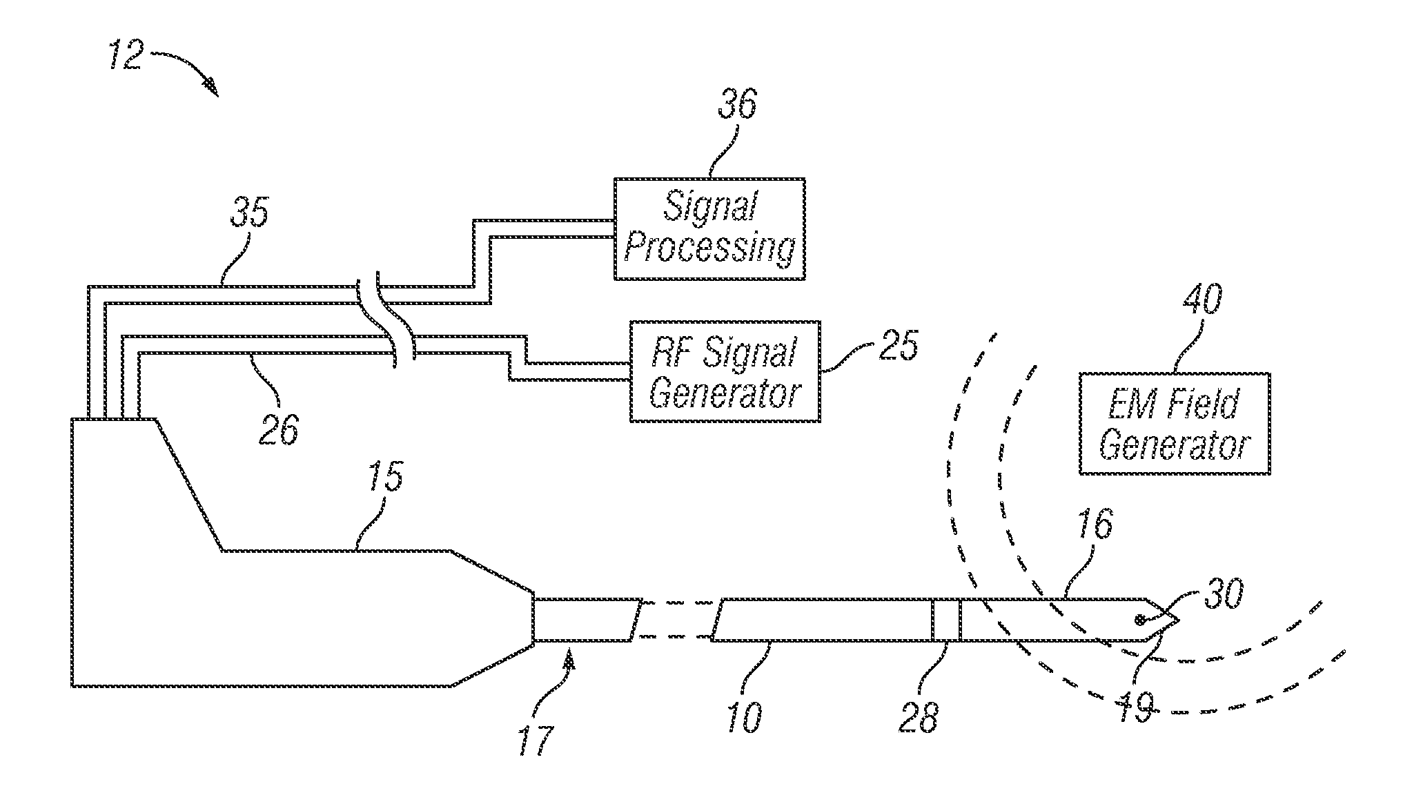
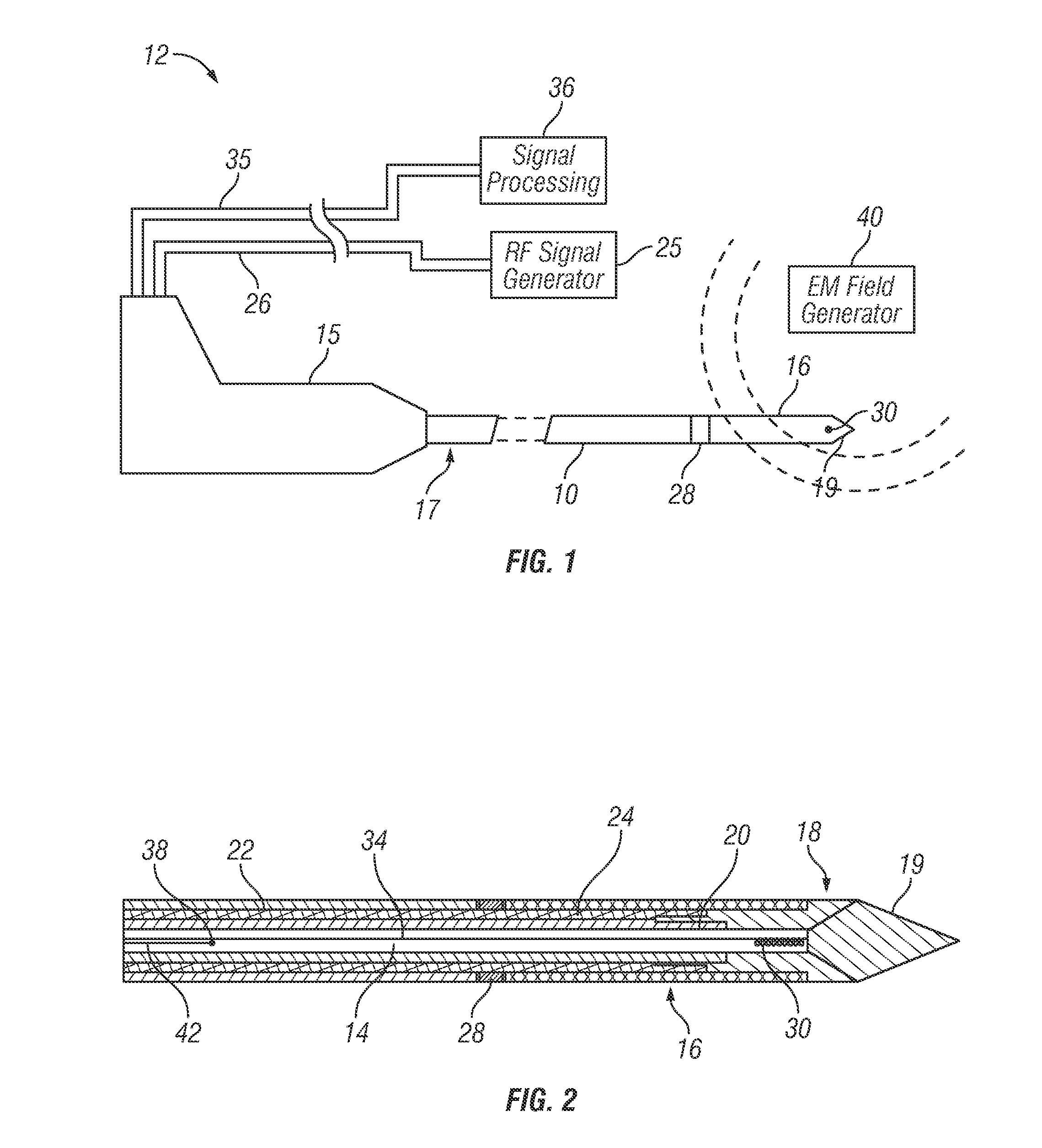
FIGS. 1 and 2 illustrate a first embodiment of a radio frequency (RF) wave guide device or probe 10 forming part of a microwave ablation and position tracking system 12. The microwave ablation system is similar to that described in co-pending application Ser. Nos. 11 / 781,467 filed on Jul. 23, 2007, 11 / 858,736 filed on Sep. 20, 2007, and 12 / 424,287 filed on Apr. 15, 2009, ...


PUM


Abstract

An RF ablation system has a hollow conductive coaxial cable comprising inner and outer coaxial tubular conductors, and an ablating member mounted at the distal end portion of the cable for delivery of radio frequency energy including microwaves to the target body tissue. The inner conductor has a central lumen and extends at least up to the ablating member. At least one electromagnetic tracking sensor coil with a magnetic core is located in the central lumen at the distal end portion of the cable, close to the distal tip of the cable, and connected to a signal processing unit. An electromagnetic field generator positioned in the vicinity of a patient undergoing treatment generates an electromagnetic field which induces a voltage in the sensor coil. The signal processing unit uses the induced voltage to calculate the position and orientation of the distal end portion or tip of the catheter in a patient's body.

Description

BACKGROUND1. Field of the InventionThe present invention generally relates to medical catheters which are used for the irradiation of biological tissues, such as devices for the ablation of biological tissues, and more particularly to such a device incorporating a tracking sensor.2. Related ArtCatheters are used for a number of procedures, including diagnostic, therapeutic, and ablative procedures. In such procedures, a catheter is moved through a patient's body to a desired treatment site. Therapeutic issue ablation systems apply energy to a biological ablation tissue site via different energy exchange means, such as heat conduction and irradiation. These systems may employ various energy modes, such as radiofrequency, ultrasound, laser, cryogenic, and the like. Within the radio frequency (RF) range, certain microwave ablation systems are used to destroy or ablate biological tissues. In one application, a microwave ablation system is used to ablate cardiac tissues that cause irregu...

Claims


Application Information

Patent Timeline
IPC IPC(8): A61B18/18
CPCA61B18/1815A61B2018/00196A61B2019/5251A61B2018/1861A61B2018/1853A61B2034/2051
Inventor ORMSBY, THEODORE C.JENN, SHEN GWOLEUNG, GEORGE L.
Owner MEDWAVE INC
Learn More