Light source device, lighting device, and display device

Inactive Publication Date: 2011-06-09
OPTO DESIGN
View PDF10 Cites 17 Cited by
  • Summary
  • Abstract
  • Description
  • Claims
  • Application Information

AI Technical Summary

Benefits of technology

[0032]According to an aspect of the present invention, the weight and the cost can be reduced because a light guiding plate that is required in a conventional technique is not required, and furthermore, uniform illumination light can be obtained over a large area. More specifically, the weight and the cost can be reduced because no light guiding plate is used, and uniform illumination light can be obtained over a large area because the reflection / transmission pattern is provided to uniformize the light emitted from the point light source. The light source device that can provide illumination light from one side or both sides can be obtained by providing the reflection / transmission pattern partially or entirely on the side reflection part, whereby the device can be used for wider applications.
[0033]According to another aspect of the present invention, the reflection / transmission pattern can be easily provided on the light-transmitting reflector plate.
[0034]According to still another aspect of the present invention, the light source device of a desired shape can be produced, whereby the device can be used for wider applications.
[0035]According to yet still another aspect of the present invention, the light-emitting diode or the laser diode is used as the point light source, whereby the service life is long, power consumption is low, and thus energy saving can be achieved for the lighting device.
[0036]According to yet still another aspect of the present invention, the lighting device and the display device having the advantageous effects of the light source device can be provided.

Problems solved by technology

If the distance is short, the outer shape of the light source may be projected on the diffusion plate to give unpleasant appearance and degrade the lighting quality.
If a highly directional light source is used, uniform illumination light may not be obtained because the brightness of a portion of the diffusion plate right above the light source becomes extremely high to generate difference in brightness between the portion and other lighting areas.
However, the use of this method causes problems in that desired illumination light cannot be obtained because the entire area proportionally becomes darker as the distance becomes larger, the device cannot be made thin, and the like.
Because the direct type lighting device has such problems, the direct type lighting devices may be difficult to be employed depending on the use.

Method used


Image

  • Light source device, lighting device, and display device
  • Light source device, lighting device, and display device
  • Light source device, lighting device, and display device

Examples


first embodiment

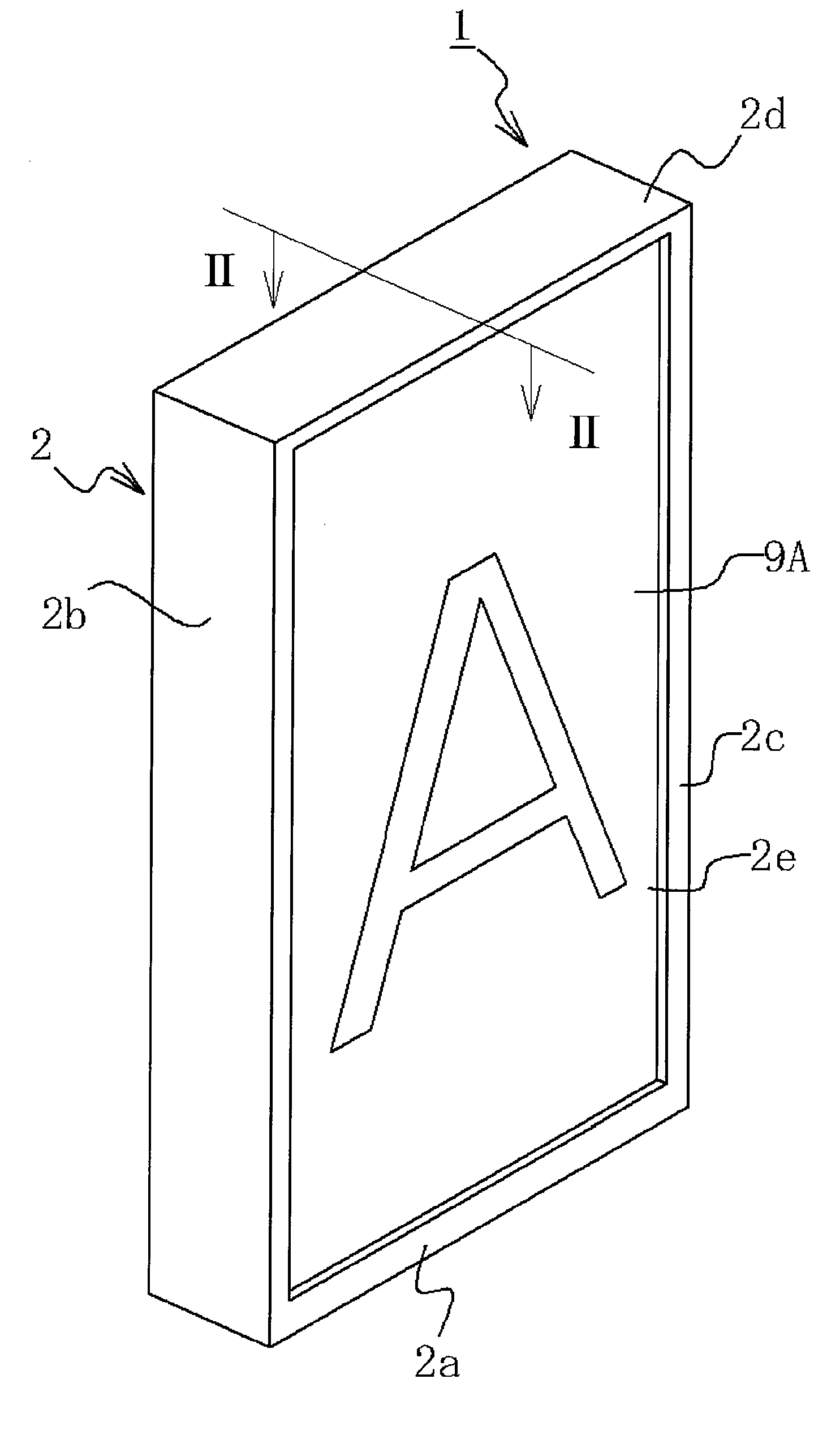
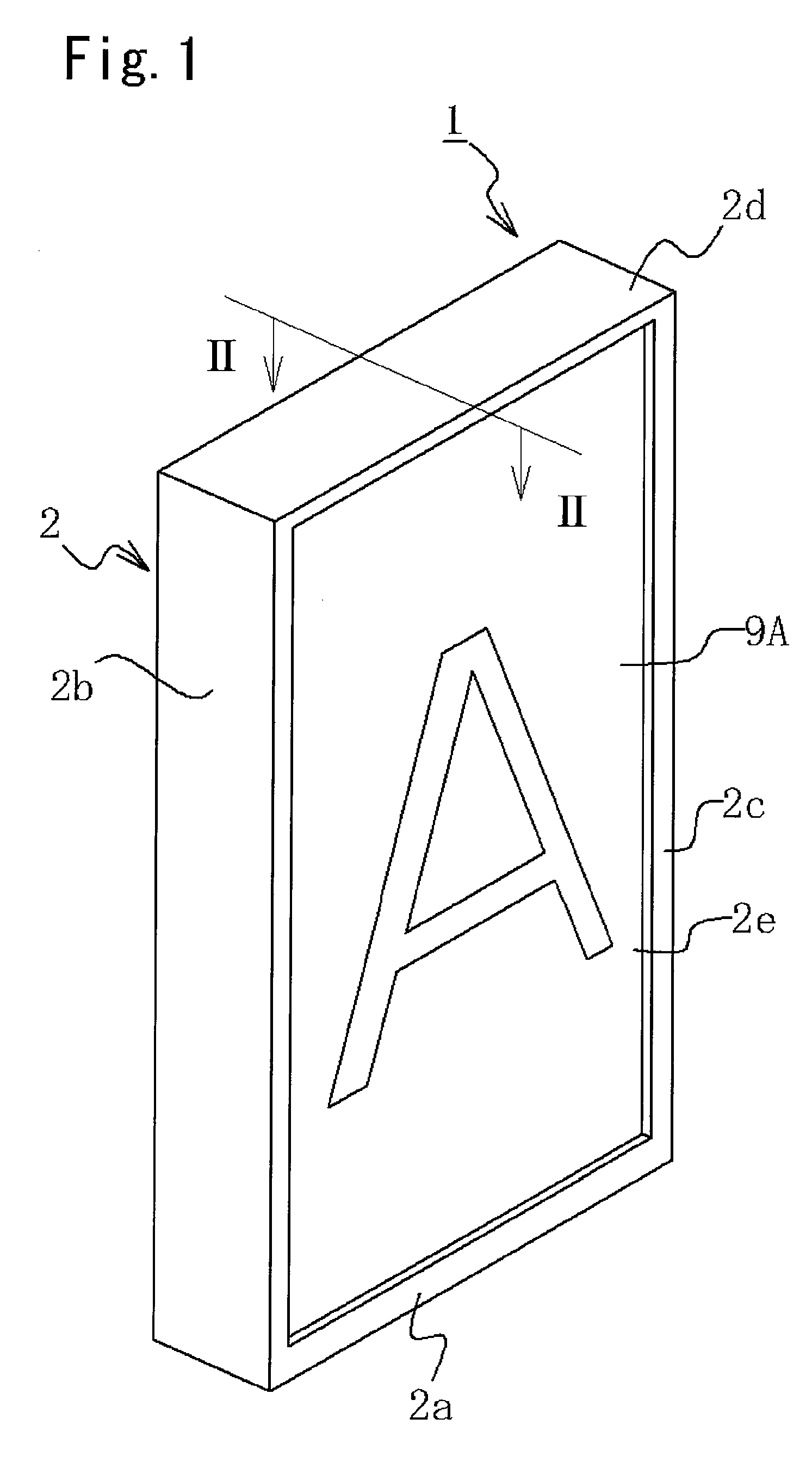
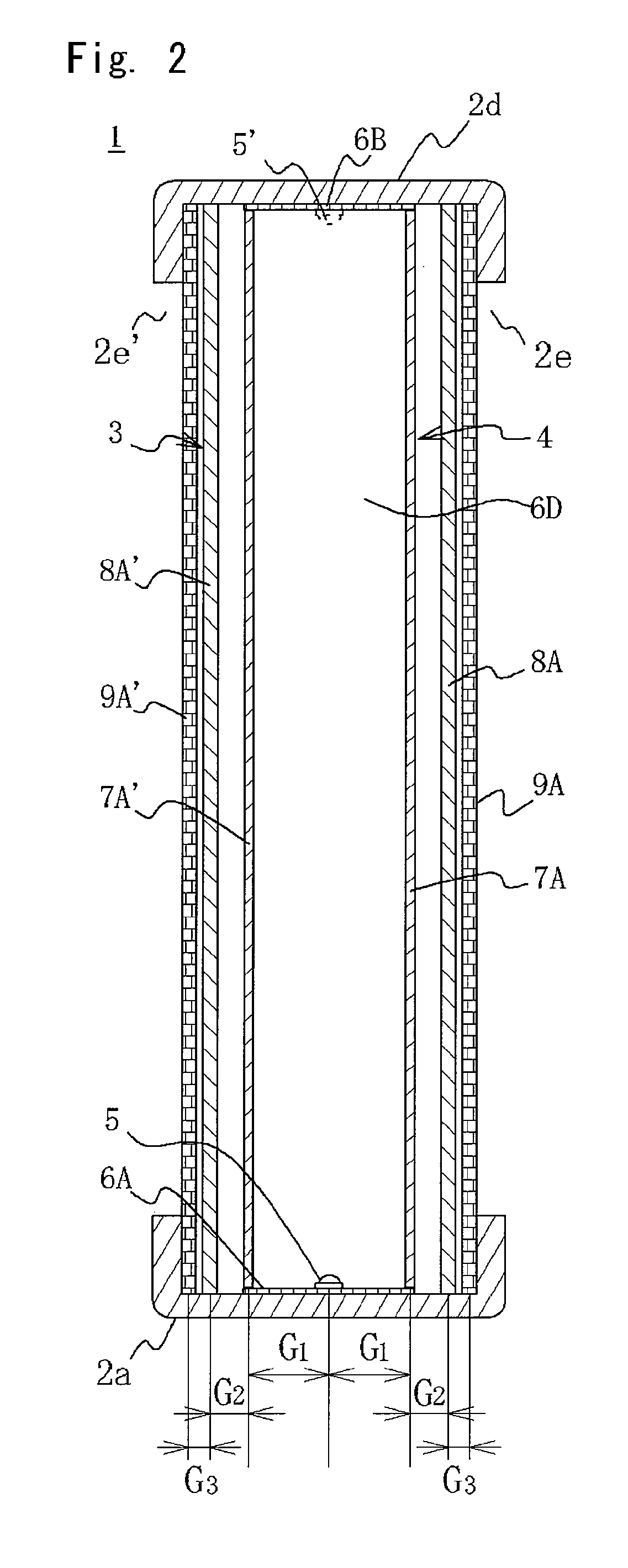
[0050]To begin with, a display device incorporating a light source device and a lighting device according to a first embodiment of the present invention is described with reference to FIG. 1 and FIG. 2. FIG. 1 is a perspective view of the display device according to the first embodiment of the present invention, and FIG. 2 is a schematic cross-sectional view of the display device in FIG. 1 taken along a line II-II.

[0051]As illustrated in FIG. 1 and FIG. 2, the display device 1 includes a frame 2 of a frame-like shape having a pair of opposing short side frames 2a and 2d and a pair of opposing long side frames 2b and 2c and being provided with windows 2e and 2e′ of a prescribed size respectively on front and rear sides, a lighting device 3 incorporated in the frame 2, and a pair of display plates 9A and 9A′ respectively fitted in the windows 2e and 2e′. The lighting device 3 includes a light source device 4 containing at least one LED 5, and a pair of diffusion plates 8A and 8A′ that...


PUM


Abstract

A light source device is equipped with a highly directional point light source, a light source installation part having a prescribed area where the point light source is installed, and a lateral reflection part that is vertically arranged to a prescribed height from the periphery of the light source installation part. The lateral reflection part is formed with a light-transmitting reflector plate that has a reflection / transmission pattern and is provided with multiple reflection / transmission parts for reflecting and at least partially transmitting light. In the reflection / transmission pattern, multiple virtual radial lines are drawn from the light source to the light-transmitting reflector plate surface at prescribed angles, and for reflection / transmission parts (Di, j) present on the radial lines that are at the same distance from the point light source, the reflectivity and transmissivity are denoted as Re1 and Tr1 when the reflection / transmission part is on a radial line at a narrow viewing angle to the point light source, and when the reflection / transmission part is on a radial line at a wide viewing angle to the point light source, the reflectivity and transmissivity are denoted as Re2 and Tr2. The relationship therebetween is set as follows: Re1>Re2 and Tr1

Description

TECHNICAL FIELD[0001]The present invention relates to a light source device, a lighting device, and a display device, and more particularly relates to a light source device using a highly directional point light source such as a light-emitting diode as a light source and a lighting device or a display device that can provide uniform illumination light over a large area using such a light source device. These devices can also be used for a backlight for a liquid crystal panel, various display devices, and the like.BACKGROUND ART[0002]In recent years, study and development of light-emitting diodes (hereinafter, referred to as “LEDs”) have rapidly advanced. Accordingly, various types of LEDs are developed, commercialized, and beginning to be used in wide range of fields. The LEDs are now being used in the field of lighting as well. Currently, in the field of lighting, the LEDs are used, for example, as a lighting device for a backlight for a liquid crystal panel, display plates and ele...

Claims


Application Information

Patent Timeline
IPC IPC(8): G09F13/04F21V7/00G02B27/20
CPCG02B6/0036G02B6/0061G02F1/133615G02B6/0096G02B6/0063
Inventor SATO, EIICHIFUKUOKA, KENJISATO, HIROYASU
Owner OPTO DESIGN
Why Eureka
Try Eureka