
Air conditioning apparatus

a technology of air conditioning apparatus and air flow rate, which is applied in the field of air conditioning apparatus, can solve the problems of reducing the flow rate of air that undergoes heat exchange with the refrigerant, the operating efficiency of the apparatus overall cannot be optimized, and the inability to achieve so as to optimize the overall operating efficiency of the apparatus. , the effect of ensuring the reliability of the compressor

Inactive Publication Date: 2011-06-09
DAIKIN IND LTD
View PDF11 Cites 22 Cited by
  • Summary
  • Abstract
  • Description
  • Claims
  • Application Information

AI Technical Summary

Benefits of technology

[0006]In this air conditioning apparatus, the quantity of the refrigerant accumulating in the condenser is adjusted by controlling the opening degree of the first expansion valve, and therefore control of the high pressure can be performed, so even in an operating condition where the temperature difference between the saturation temperature of the refrigerant in the condenser and the temperature of the air is small and where it is easy for the heat exchange efficiency in the condenser to drop, like, for example, when the outside air temperature is high, the high pressure can be raised and a situation where the heat exchange efficiency in the condenser drops can be suppressed. Further, also with respect to hunting between steps of the air flow rate of the blower fan when the outside air temperature is low, in a situation where the high pressure falls too much in a step where the air flow rate is large, the high pressure can be maintained by accumulating the refrigerant in the condenser, and in a situation where the high pressure rises too much in a step where the air flow rate is small, the high pressure can be maintained by decreasing the refrigerant accumulating in the condenser.
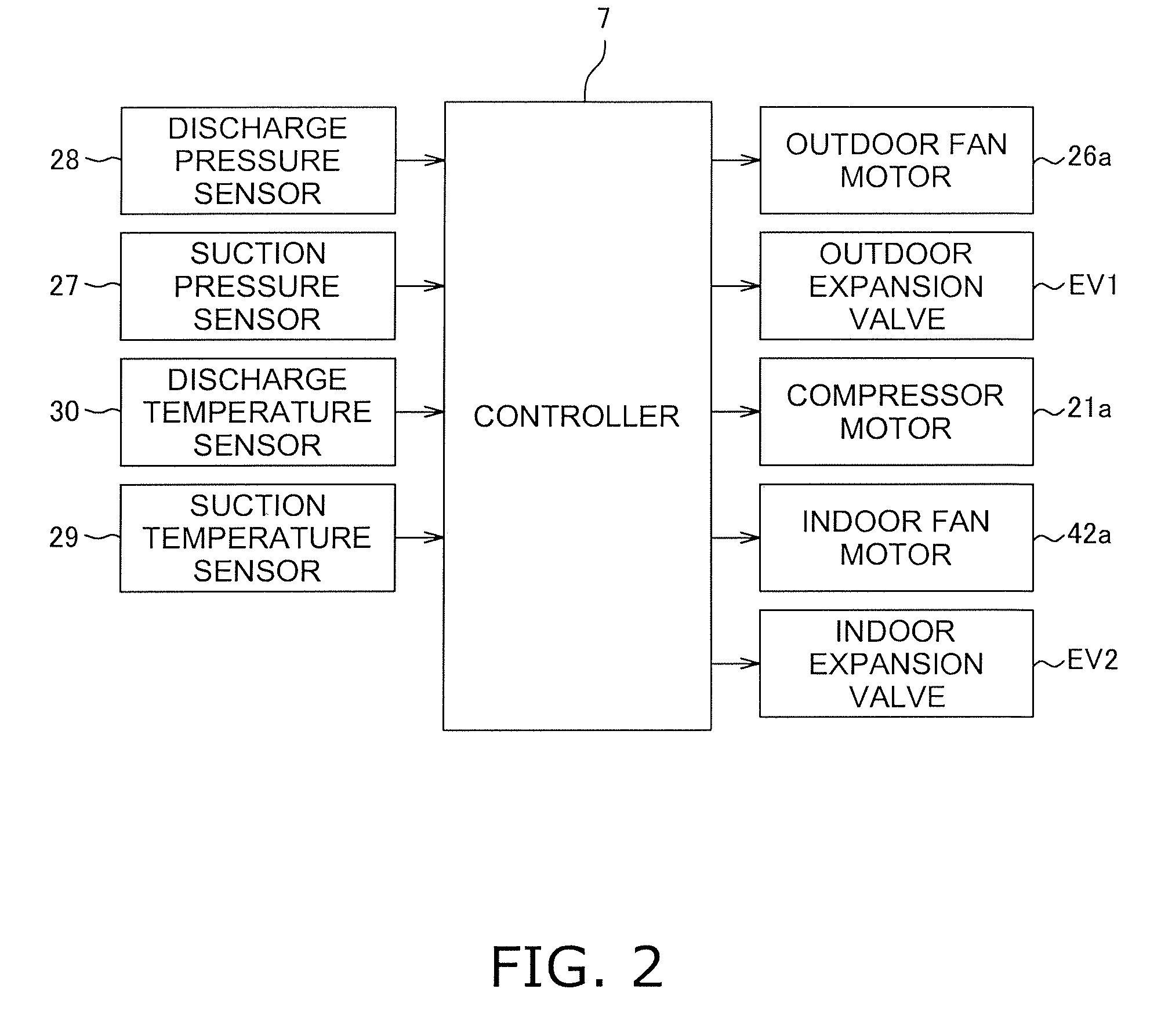
[0009]In this air conditioning apparatus, control is performed such that the high pressure becomes the target high pressure by opening degree control of the first expansion valve, and basically opening degree control of the first expansion valve becomes performed preferentially over air flow rate control of the blower fan because the prescribed air flow rate of the blower fan is changed when the high pressure does not become the target high pressure by just opening degree control of the first expansion valve, so the high pressure can be controlled even more finely.
[0012]In this manner, in this air conditioning apparatus, even though control is performed such that the high pressure becomes the target high pressure by jointly using opening degree control of the first expansion valve together with air flow rate control of the blower fan, it becomes difficult for the quantity of the refrigerant in the portion of the refrigerant circuit from the second expansion valve via the evaporator to the compressor to fluctuate because the receiver that can accumulate the refrigerant is connected between the first expansion valve and the second expansion valve, and therefore it can be made difficult for the control to affect the operating state of the evaporator or the compressor.
[0014]In this air conditioning apparatus, it can be made difficult for the quantity of the refrigerant in the portion of the refrigerant circuit from the second expansion valve via the evaporator to the compressor to fluctuate because of the receiver, and the quantity of the refrigerant in the evaporator and the state of the refrigerant in the outlet of the evaporator can be stabilized by opening degree control of the second expansion valve, so the operating efficiency of the apparatus overall can be optimized and the reliability of the compressor can be improved (e.g., out-of-gas operation and wet compression can be prevented).

Problems solved by technology

Particularly when the outside air temperature is high, the heat exchange efficiency in the condenser drops because the temperature difference between the saturation temperature of the refrigerant in the condenser and the temperature of the air becomes smaller, and therefore there is the fear that the operating efficiency of the apparatus overall cannot be optimized.
To counter this, it is conceivable to lower the air flow rate of the blower fan in order to raise the high pressure in the refrigeration cycle; however, although this can raise the saturation temperature of the refrigerant in the condenser and increase the temperature difference with the air, this decreases the flow rate of the air that undergoes heat exchange with the refrigerant, so it is difficult to increase the heat exchange duty itself in the condenser.
Further, when the outside air temperature is low, it is conceivable to decrease the heat exchange duty in the condenser by lowering the air flow rate of the blower fan in order to maintain the high pressure in the refrigeration cycle operation; however, the apparatus ends up structurally resonating when the air flow rate is linearly changed, and control is complex, so it is necessary to control the air flow rate stepwise in plural stages.
However, when the air flow rate is controlled stepwise in plural stages, the high pressure that is to be in balance between each step differs, so this results in hunting between steps and it becomes difficult for control stability to be obtained.

Method used


Image

  • Air conditioning apparatus
  • Air conditioning apparatus
  • Air conditioning apparatus

Examples


Embodiment Construction

[0022]An embodiment of an air conditioning apparatus pertaining to the present invention will be described below on the basis of the drawings.

(1) Configuration of Air Conditioning Apparatus

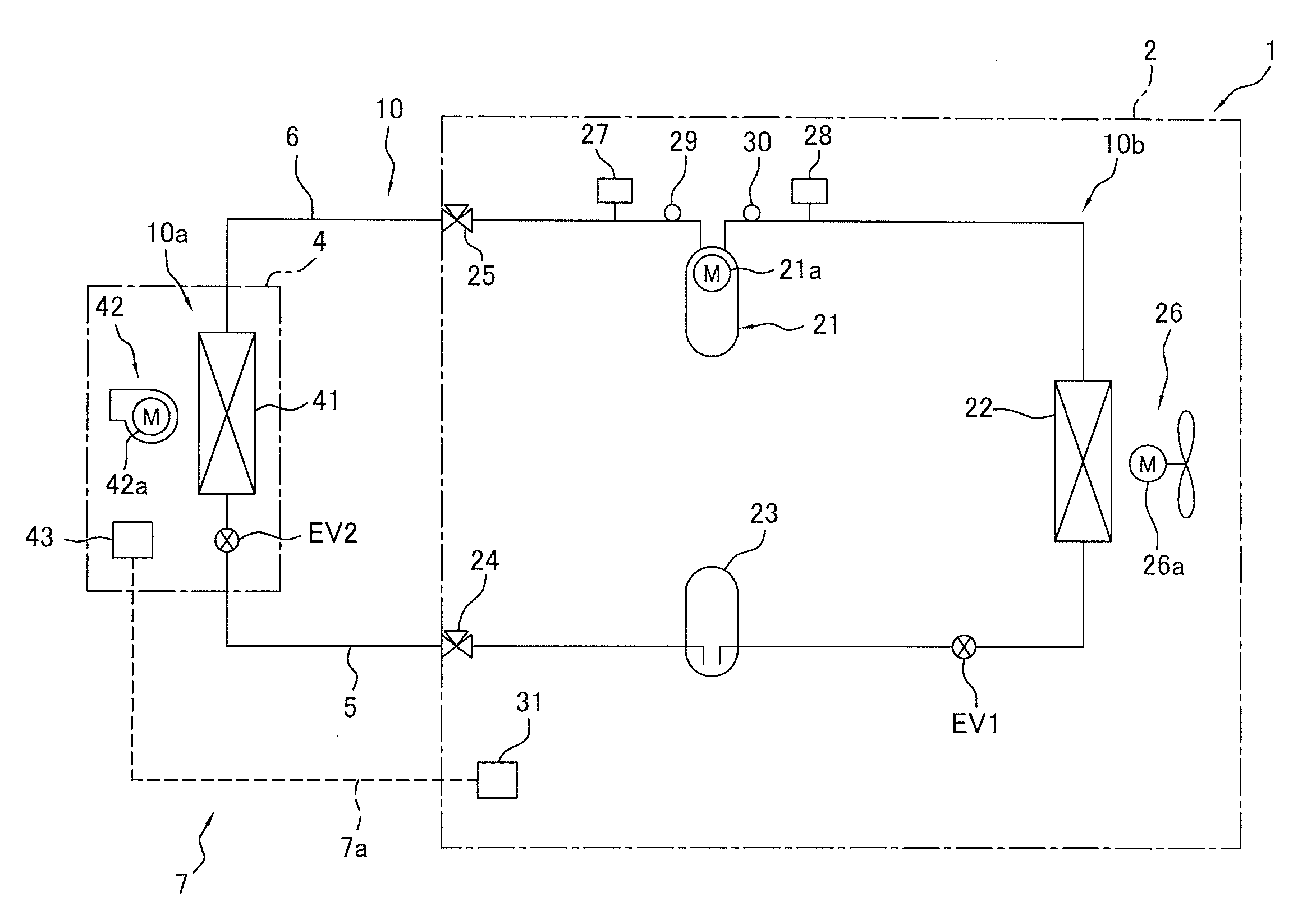
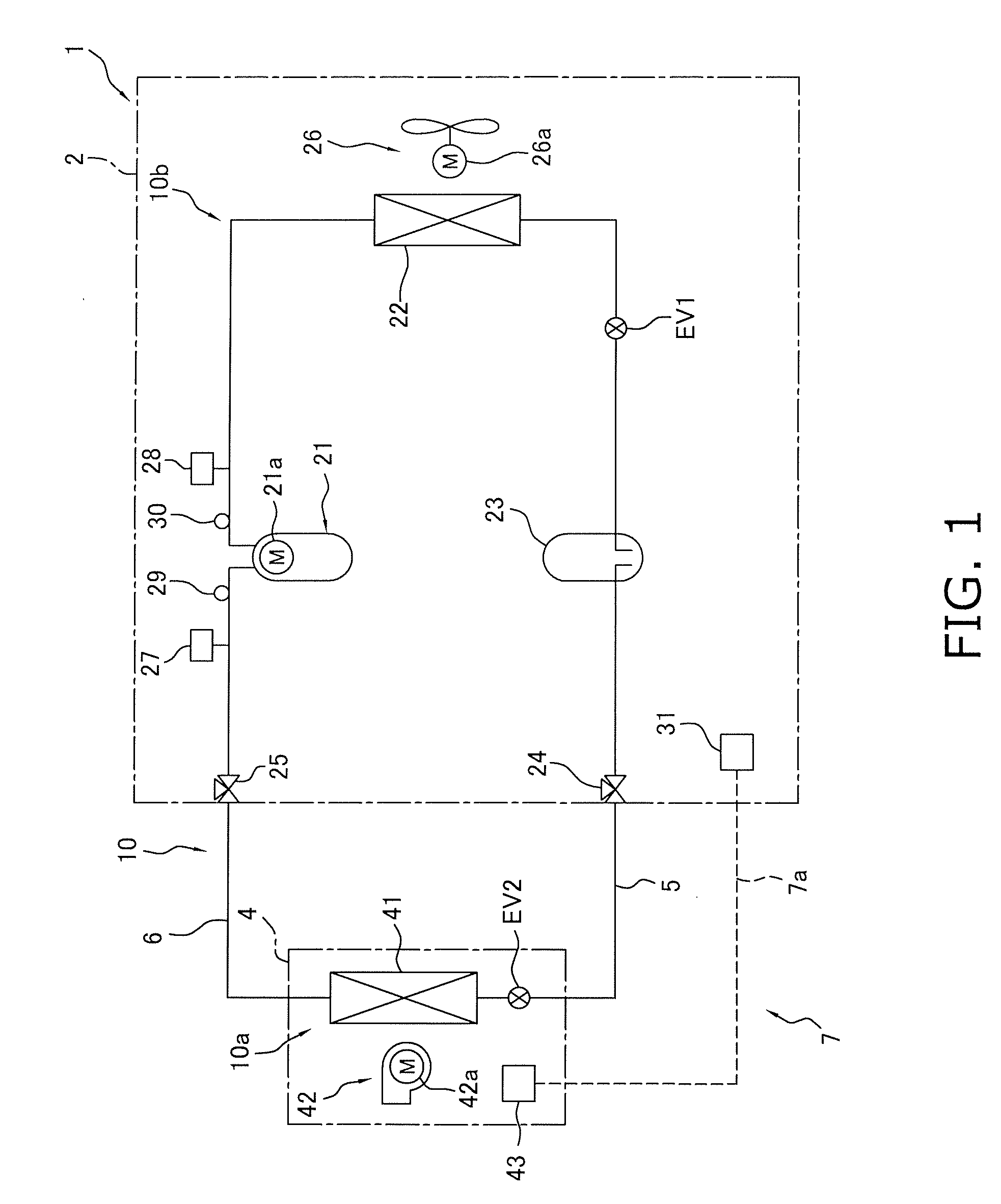
[0023]FIG. 1 is a general configuration diagram of an air conditioning apparatus 1 pertaining to the embodiment of the present invention. The air conditioning apparatus 1 is an apparatus used to cool the inside of a room in a building or the like by performing a vapor compression refrigeration cycle operation. The air conditioning apparatus 1 is mainly equipped with an outdoor unit 2, an indoor unit 4, and a liquid refrigerant connection pipe 5 and a gas refrigerant connection pipe 6 that interconnect the outdoor unit 2 and the indoor unit 4. That is, a vapor compression refrigerant circuit 10 of the air conditioning apparatus 1 of the present embodiment is configured as a result of the outdoor unit 2, the indoor unit 4, and the liquid refrigerant connection pipe 5 and the gas refrigerant connecti...


PUM


Abstract

An air conditioning includes a refrigerant circuit and a blower fan. The refrigerant circuit has a compressor, a condenser, a first expansion valve, a second expansion valve, and an evaporator sequentially connected. The blower fan is arranged and configured to supply air as a heat source to the condenser. An air flow rate of the blower fan and an opening degree of the first expansion valve are controlled such that high pressure in a refrigeration cycle operation of the refrigerant circuit becomes a target high pressure.

Description

TECHNICAL FIELD[0001]The present invention relates to an air conditioning apparatus and particularly to an air conditioning apparatus that is equipped with a blower fan that supplies air as a heat source to a condenser that configures a refrigerant circuit and which air conditioning apparatus can control the air flow rate of the blower fan such that high pressure in a refrigeration cycle operation becomes a target high pressure.BACKGROUND ART[0002]Conventionally, there has been an air conditioning apparatus that is equipped with a blower fan that supplies air as a heat source to a condenser that configures a refrigerant circuit and which air conditioning apparatus controls the air flow rate of the blower fan such that high pressure in a refrigeration cycle operation becomes a target high pressure (see JP-A No. 1-225852 as patent literature 1).SUMMARY OF THE INVENTION[0003]However, in the aforementioned air conditioning apparatus, ensuring that the high pressure can be controlled mor...

Claims


Application Information

Patent Timeline
Patent Type & Authority Applications(United States)
IPC IPC(8): F25D17/06F25D17/02
CPCF24F11/0079F25B2313/005F24F2011/0045F25B49/027F25B2341/0662F25B2400/16F25B2600/021F25B2600/111F25B2600/21F25B2600/2513F25B2700/1931F25B2700/1933F25B2700/21151F25B2700/21152Y02B30/741Y02B30/743Y02B30/746F24F2011/0043F24F11/77F24F2140/12F24F2140/20F25B41/39Y02B30/70
Inventor KOJIMA, AKIHARU
Owner DAIKIN IND LTD
Learn More