Method of friction welding of a piston having a cooling duct

a technology of cooling duct and friction welding, which is applied in the direction of welding devices, soldering devices, manufacturing tools, etc., to achieve the effect of saving production steps

Inactive Publication Date: 2011-06-09
GESENKSCHMIEDE SCHNEIDER GMBH
View PDF0 Cites 18 Cited by
  • Summary
  • Abstract
  • Description
  • Claims
  • Application Information

AI Technical Summary

Benefits of technology

[0014]In order to reduce the weld bead to a certain size in certain applications and to have to use only certain chipping or turning tools, the connected parts are assembled at least on one side by friction welding with no weld bead or with a very small weld bead. Thereby a weld bead can be completely eliminated within a predetermined width size.
[0015]In order to achieve a uniform expansion when the friction welded part is heated and a long life cycle and good insertion characteristics, the material of the first and the skirt member are identical.

Problems solved by technology

This should allow an undisturbed oil circulation (all weld beads limiting the oil flux are disadvantageous for cooling).

Method used


Image

  • Method of friction welding of a piston having a cooling duct
  • Method of friction welding of a piston having a cooling duct
  • Method of friction welding of a piston having a cooling duct

Examples


second embodiment

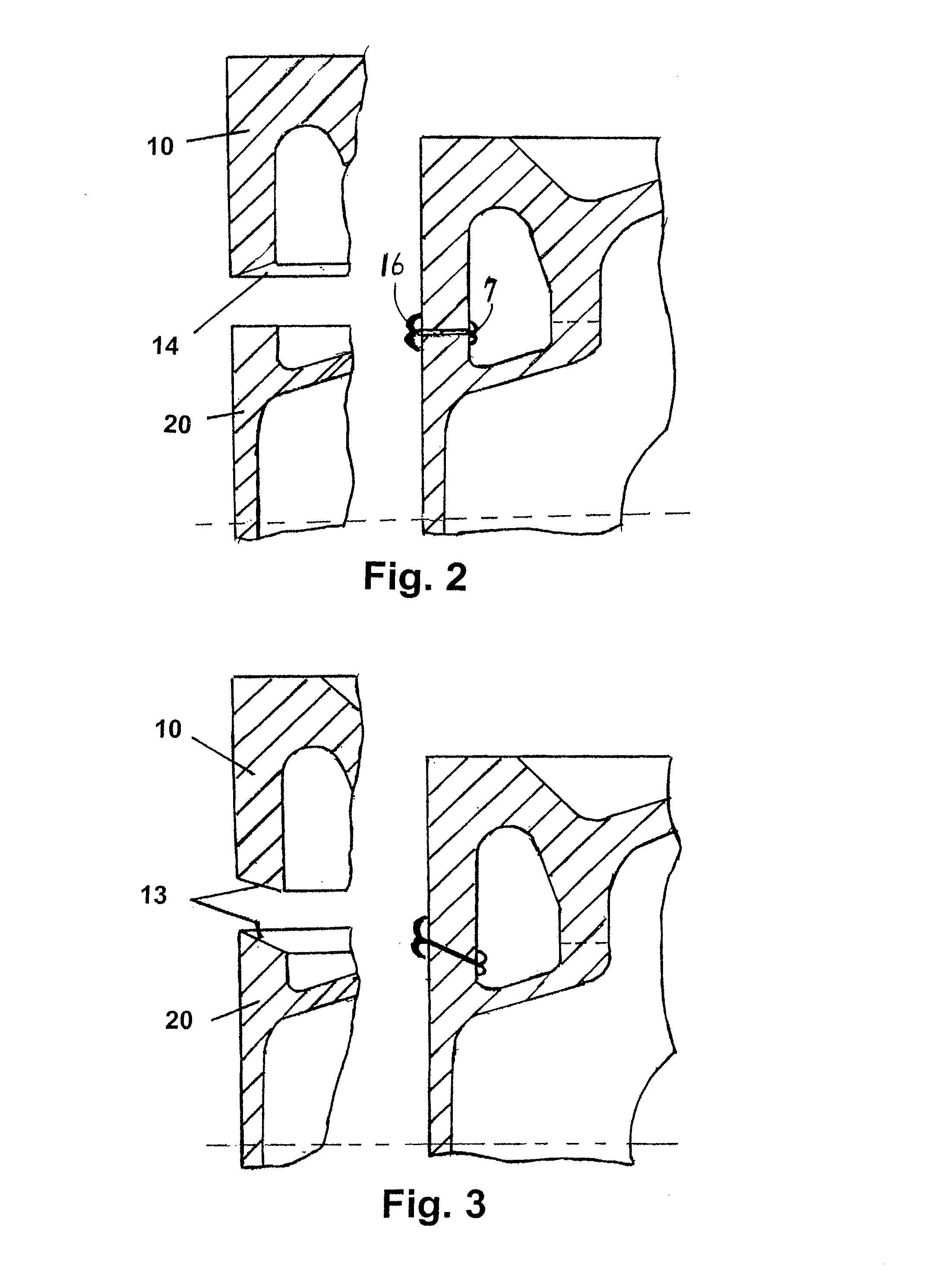
[0031]FIG. 3 shows a section of an external wall of a piston before and after the friction welding process, wherein in this case the external wall of the piston is designed so that both the surfaces to be welded are arranged in an angle one to the other so that the material accumulation is formed on the external side of the piston.

third embodiment

[0032]FIG. 4 shows a section of an external wall of a piston before and after the friction welding process, wherein in this case there is an opening in the area of the oil duct inside the piston walls, in which the material of the weld bead can be accumulated after that, without limiting the internal width of the oil duct.

fourth embodiment

[0033]FIG. 5 shows a section of the walls of an head and shirt part of the piston made of near-fit profiles before and after the friction welding process, wherein in the area of the oil duct there is substantially less material accumulation.


PUM

PropertyMeasurementUnit
angleaaaaaaaaaa
angleaaaaaaaaaa
angleaaaaaaaaaa

Abstract

A method of friction welding a head part to a skirt part of a piston having a hollow cooling duct in which the internal connection surface of the first part to be welded is reciprocally arranged with an internal connection surface of the second part to be friction welded, so that they form a unsymmetrical contact area, so that the resulting weld of the first and the second parts produces a weld bead that is located predominantly outside of the hollow cooling duct. The unsymmetrical contact area can be formed by chamfered, angled edge surfaces that produce, for example, a wedge-shaped space, or partially matched, inter-fitting surfaces that remain out of contact and produce a gap at sides facing the hollow space.

Description

CROSS REFERENCE TO RELATED APPLICATION[0001]This application is a continuation-in-part of commonly owned, co-pending U.S. patent application Ser. No. 12 / 349,259, filed Jan. 6, 2009.BACKGROUND OF THE INVENTION [0002]1. Field of the Invention[0003]The present invention relates to a method for welding a piston head member with a piston skirt member of a piston with a cooling duct by friction welding, wherein the hollow space of the cooling duct preferably contains no protruding welding beads.[0004]2. Description of Related Art[0005]The connection between two parts of a piston having a cooling duct by friction welding is known. International Patent Application WO 2006 / 034862 A1 teaches a piston having a cooling duct, where the piston head is connected with the piston skirt member by friction welding the walls of the cooling duct resulting in weld beads on both sides of the weld. The aforesaid weld beads in the cooling duct negatively influence the cooling medium.[0006]From German Patent...

Claims


Application Information

Patent Timeline
Patent Type & Authority Applications(United States)
IPC IPC(8): B23K20/12B23K31/02
CPCB23K20/129B23K33/006B23K33/008F02F2003/0061B23K2201/003F02F3/003F02F3/22B23K37/06B23K2101/003
Inventor KOLBE, PETERSCHMITZ, ERNST-PETER
Owner GESENKSCHMIEDE SCHNEIDER GMBH
Why Eureka
Try Eureka