
Multi-function paper toweling dispenser

a multi-functional, paper towel dispenser technology, applied in the field of multi-functional paper towel dispensers, can solve the problems of tabbing, tabbing also becomes a particular problem, tabbing, etc., and achieve the effect of reducing the pull for

Inactive Publication Date: 2011-06-09
DISPENSING DYNAMICS INT
View PDF3 Cites 30 Cited by
  • Summary
  • Abstract
  • Description
  • Claims
  • Application Information

AI Technical Summary

Benefits of technology

The present invention is a multi-function paper towel dispenser that can be selectively operated in different modes using a plurality of alternative operational modes. The dispenser is characterized by its versatility, ease of use, and reliability in any of the operational modes selected. The modes include a paper hidden mode and a paper exposed mode, which both utilize sensor structure and electronic control circuitry to operate an electric motor driven rotatable toweling support roller to partially cut and dispense the paper toweling. The electric motor is also utilized when not employing the sensor structure, in a hybrid mode where a pull force exerted on the toweling tail initiates rotation of the toweling support roller, and the motor then reduces the pull force required for final dispensing of a towel. The sensor structure is operatively associated with the electric motor to activate it and cause rotation of the toweling support roller to transport the paper toweling for dispensing. The electronic control circuitry for operating the dispenser in either the first or second mode of operation utilizes simple, reliable mechanical switches as compared to programmable logic controllers, which simplifies the design and reduces costs. The invention also incorporates energy saving features and a one-way clutch interconnection between a toweling support roller and a manually rotatable handle, which allows the handle to rotate the roller in a single direction only.

Problems solved by technology

The apparatus of U.S. Pat. Nos. 6,314,850 and 6,553,879 has met with considerable commercial success; however, some problems with “tabbing” have occurred during use of the dispenser.
Tabbing also becomes a particular problem when low basis weight paper is to be dispensed.
It is not an exaggeration to say that virtually all paper towel dispensers of a purely mechanical nature which rely on direct pulling of the toweling by a user to transport the toweling and actuate moveable cutter or severing blades have a tabbing problem to some extent.

Method used


Image

  • Multi-function paper toweling dispenser
  • Multi-function paper toweling dispenser
  • Multi-function paper toweling dispenser

Examples


Embodiment Construction

Referring now to the drawings, a multi-function paper towel dispenser constructed in accordance with the teachings of the present invention is illustrated. As explained and disclosed in greater detail below, the dispenser is selectively operable to dispense paper toweling from a roll of paper toweling employing a plurality of alternative operational modes.

The paper towel dispenser includes a housing 10 (shown in FIGS. 3, 9-10, 13, 14, 17, 19 and 22-26), the housing having a towel dispensing opening 12 at the bottom thereof.

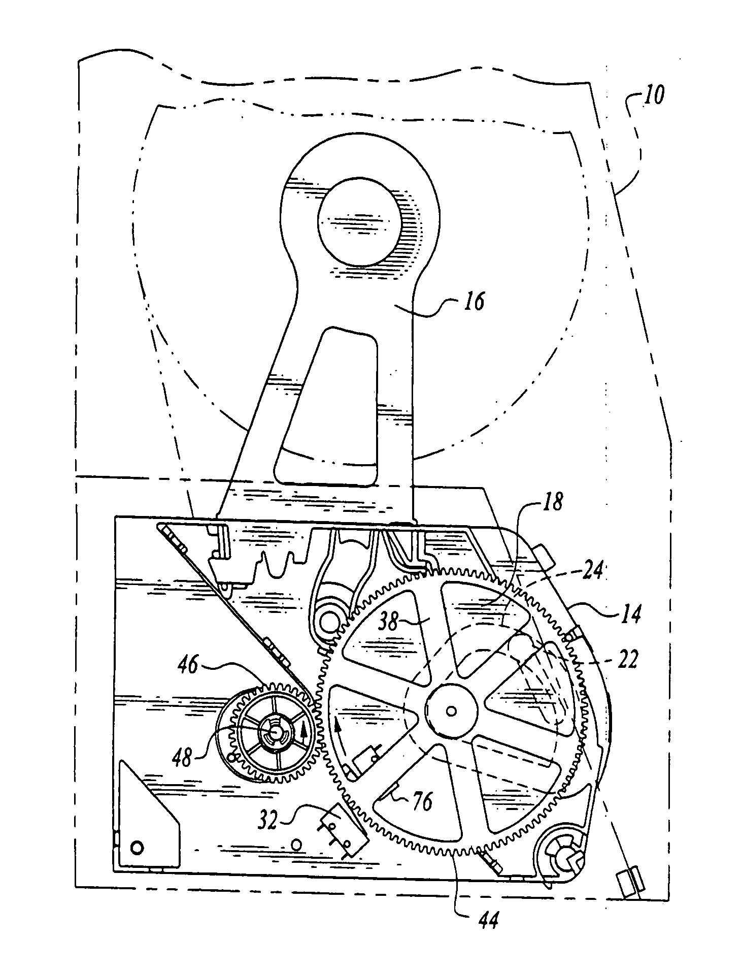
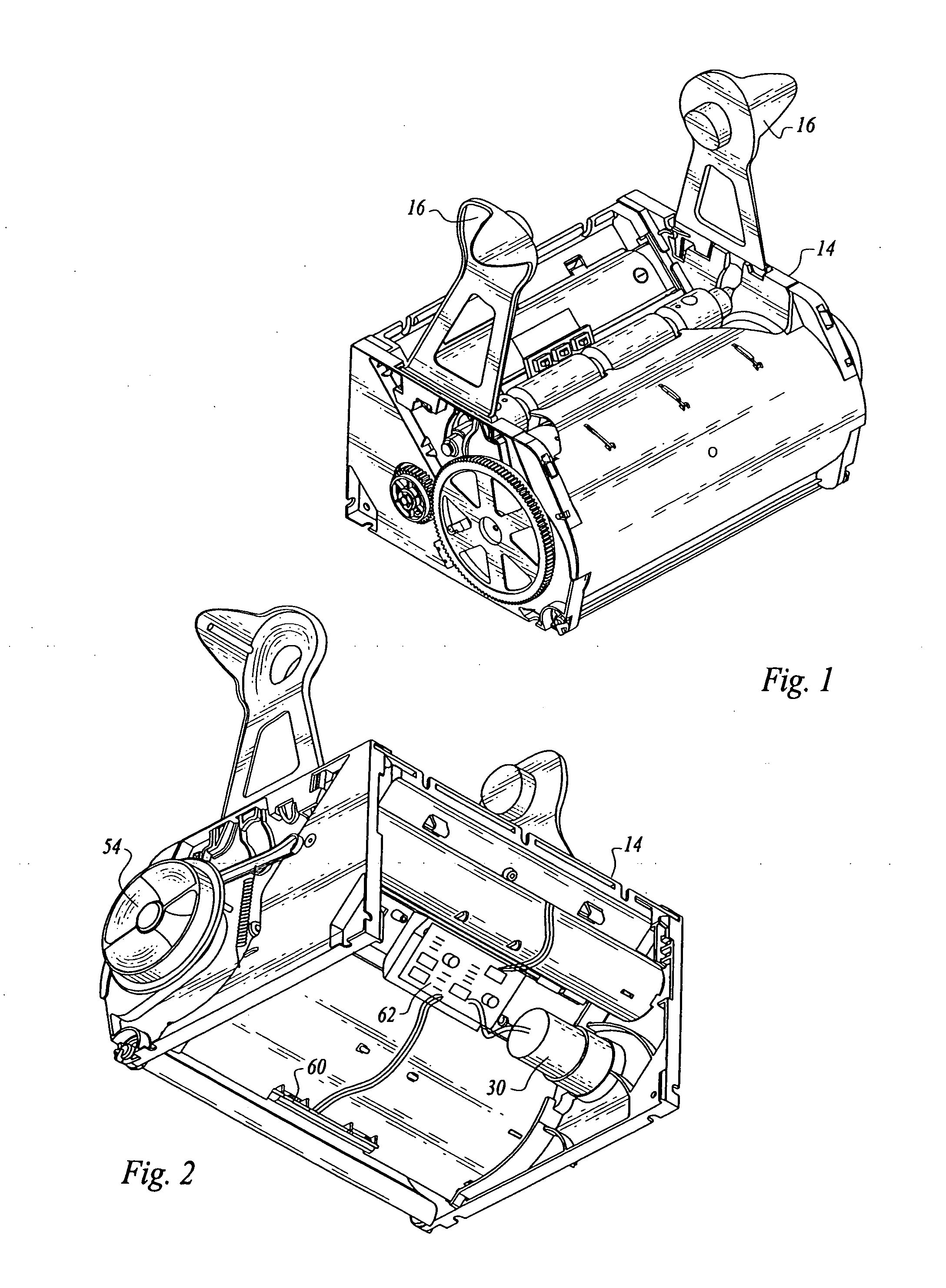
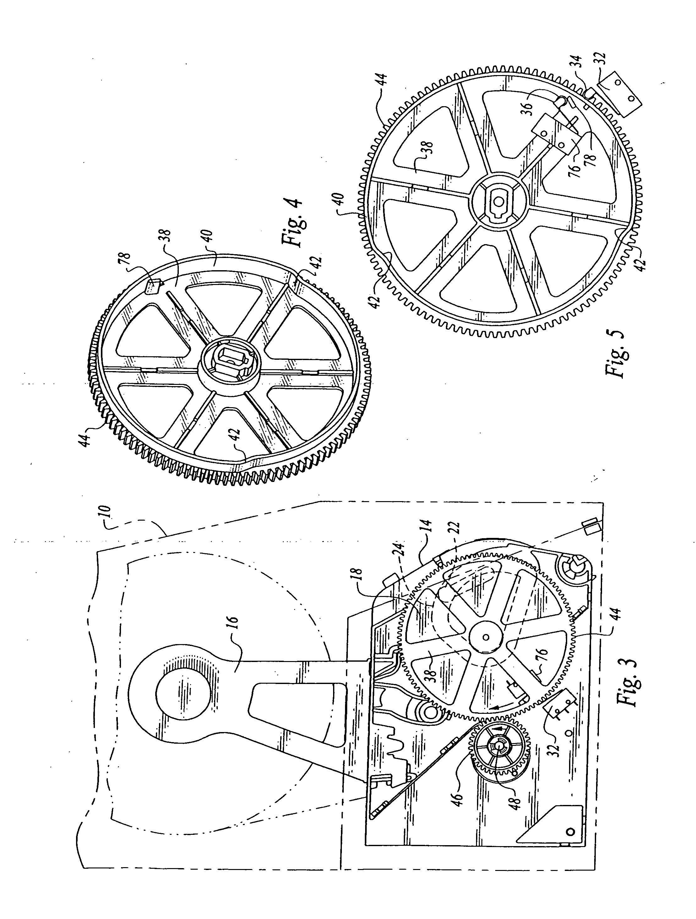
Mounted in the interior of the housing 10 is an assembly 14 (see FIGS. 1-3) including operational structural components of the multi-function paper towel dispenser. These structural elements include a roll support in the form of spaced support arms 16 insertable into the open ends of a supply roll of paper toweling in a conventional fashion.

A rotatable toweling support roller 18 has a cylindrically-shaped outer peripheral surface and is rotatable in a predetermine...


PUM


Abstract

In a toweling dispenser, an electric motor driven toweling support roller and a handle for rotating the toweling support roller are connected by a one-way clutch, which allows the handle to rotate the toweling support roller only in a single direction of rotation when the electric motor does not drive the toweling support roller, the single direction transporting toweling on the toweling support roller to an exit opening of the dispenser.

Description

TECHNICAL FIELDThis invention relates to apparatus selectively operable to dispense paper toweling from a roll of paper toweling employing a plurality of alternative operational modes. The apparatus includes an interconnection between a towel support roll and a manually movable handle including a one-way clutch whereby the handle can only rotate the roller in a single direction of rotation.BACKGROUND OF THE INVENTIONMany dispenser systems are known in the prior art for dispensing paper toweling from rolls thereof. In some cases, the paper toweling is comprised of individual paper towel segments separated by perforated tear lines, and in others the toweling has no perforated tear lines formed therein, severing or cutting individual sheets from the toweling accomplished by some suitable severing structure incorporated in the dispenser.Many towel dispensers of a purely mechanical nature have been developed and utilized over the years for dispensing paper towels, including dispensers wh...

Claims


Application Information

Patent Timeline
Patent Type & Authority Applications(United States)
IPC IPC(8): A47K10/38A47K10/26
CPCA47K10/34
Inventor KEILY, JOEL P.CVJETKOVIC, NIKO ANTHONY
Owner DISPENSING DYNAMICS INT
Learn More