
Motor drive system for hybrid vehicle and method for controlling the same

a technology of hybrid vehicles and motor drives, which is applied in the direction of engine-driven generators, electric devices, transportation and packaging, etc., can solve the problems of excessive rotation and counter-electromotive force suitably applied, increase in hybrid system manufacturing costs, etc., and achieve the effect of preventing the occurrence of failur

Inactive Publication Date: 2011-06-09
HYUNDAI MOTOR CO LTD
View PDF19 Cites 14 Cited by
  • Summary
  • Abstract
  • Description
  • Claims
  • Application Information

AI Technical Summary

Benefits of technology

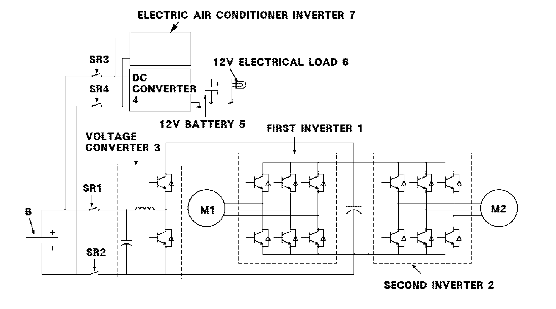
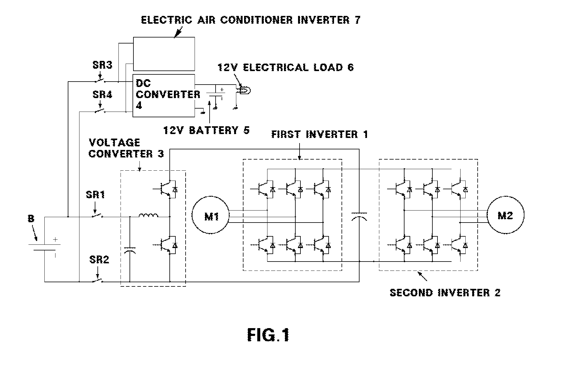
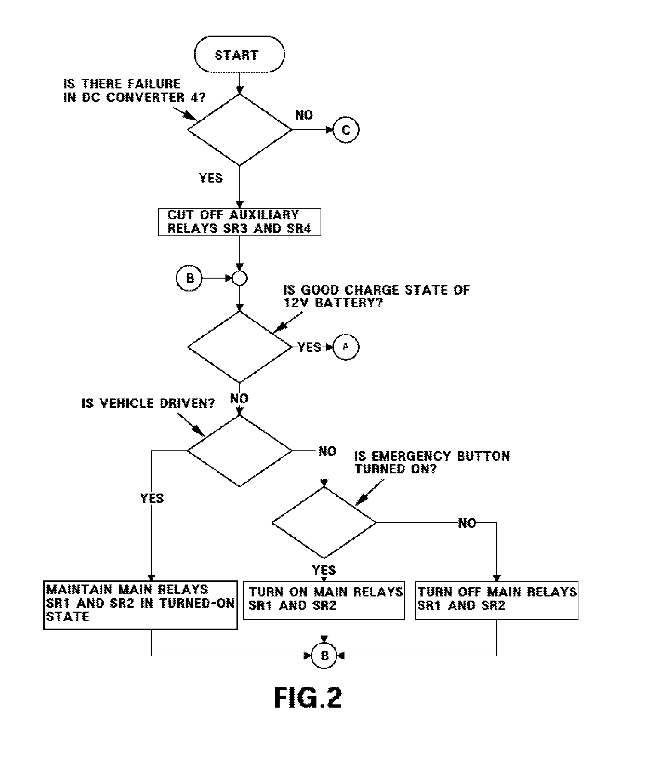
[0016]The present invention provides a motor drive system for a hybrid vehicle and a method for controlling the same, in which non-powertrain components such as a DC converter and an electric air conditioner inverter are suitably connected between a DC battery and a main relay through an auxiliary relay so as to suitably prevent a counter electromotive force generated from a motor during turn-off of a main relay from being applied to the DC converter and the electric air conditioner inverter, thus protecting the non-powertrain components and suitably preventing the occurrence of failure. In preferred exemplary embodiments, even in the event of a failure in the DC converter, the motor drive system for a hybrid vehicle and the method for controlling the same of the present invention can quickly cope with the failure by suitably controlling the auxiliary relay.
[0018]In a preferred embodiment, the motor drive system of the present invention may further include a controller for suitably controlling the operation of the first and second main relays and that of the first and second auxiliary relays to cut off the electrical effect between the non-powertrain components such as the DC converter and the electric air conditioner inverter and powertrain components such as the first and second inverters.
[0020]In a preferred embodiment, the method of the present invention may further include suitably preventing an overvoltage due to a counter electromotive force of the motor from being applied to the DC converter at the moment when the first and second main relays are turned off even though the first and second auxiliary relays are turned on.

Problems solved by technology

Therefore, it is necessary to increase the maximum withstanding voltage of the non-powertrain components such as the DC converter 4 and the electric air conditioner inverter 7, which causes an increase in manufacturing cost for a hybrid system according to the high withstanding voltage and also causes deterioration in the efficiency of the system.
Further, the first and second motors M1 and M2 including an electric generator are out of control during high speed operation of the engine, and thereby excessive rotation and counter electromotive force may be suitably applied to the electric generator.
As a result, the possibility that the rotating part of the motor may be out of order and the inverter may be burnt out due to overvoltage is increased.
Furthermore, in examples where the vehicle is stopped after the first and second main relays SR1 and SR2 are turned off, since the driving force of the first and second motors M1 and M2 is lost, the vehicle cannot be started and cannot enter a limp-home mode for vehicle diagnosis.
As a result, although the 12V power supply by the 12V auxiliary battery is available, the vehicle cannot be started, and it has to be towed away.
Accordingly, it is necessary to apply the power to an IGBT gate drive circuit to suitably maintain the IGBT in a turned-off state, which reduces the durability of the gate drive circuit.

Method used


Image

  • Motor drive system for hybrid vehicle and method for controlling the same
  • Motor drive system for hybrid vehicle and method for controlling the same
  • Motor drive system for hybrid vehicle and method for controlling the same

Examples


Embodiment Construction

[0032]In a first aspect, the present invention features a motor drive system for a hybrid vehicle, the system comprising first and second motors for driving the vehicle, first and second inverters for driving the first and second motors, respectively, a DC battery for outputting a DC voltage, a voltage converter for stepping up the DC voltage from the DC battery and supplying the stepped up voltage to the first and second inverters or for stepping down the DC voltage from the first and second inverters and supplying the stepped down voltage to the DC battery, first and second main relays connected between the DC battery and the voltage converter, and a DC converter and an electric air conditioner inverter as non-powertrain components connected between the DC battery and the first and main relays through first and second auxiliary relays.

[0033]IN another aspect, the present invention features a method for controlling a motor drive system for a hybrid vehicle, the method comprising de...


PUM


Abstract

The present invention provides a motor drive system for a hybrid vehicle and a method for controlling the same, which can prevent a counter electromotive force generated from a motor during turn-off of a main relay from being applied to non-powertrain components such as a DC converter and an electric air conditioner inverter, thus protecting the non-powertrain components and preventing the occurrence of failure.

Description

CROSS-REFERENCE TO RELATED APPLICATION[0001]This application claims under 35 U.S.C. §119(a) the benefit of Korean Patent Application No. 10-2009-0119489 filed Dec. 4, 2009, the entire contents of which are incorporated herein by reference.BACKGROUND[0002](a) Technical Field[0003]The present disclosure relates, generally, to a motor drive system for a hybrid vehicle and to a method for controlling the same. More particularly, the present invention relates to a motor drive system for a hybrid vehicle and a method for controlling the same, which can suitably prevent a counter electromotive force generated from a motor during turn-off of a main relay from being applied to non-powertrain components, such as a DC converter and an electric air conditioner inverter, thus protecting the non-powertrain components and preventing the occurrence of failure.[0004](b) Background Art[0005]Hybrid vehicles employ an electric motor as an auxiliary power source as well as a gasoline engine to provide a...

Claims


Application Information

Patent Timeline
IPC IPC(8): B60L1/00B60L3/04B60L50/16B60W20/00
CPCY02T10/7225Y02T10/648B60L3/003Y02T10/7258B60L2210/14B60W20/50B60L3/04Y02T10/64Y02T10/72B60W10/08B60W20/00B60W10/30
Inventor SONG, HONG SEOK
Owner HYUNDAI MOTOR CO LTD
Learn More