Time measurement circuit

a time measurement and circuit technology, applied in the field of time measurement technique, can solve the problem of reducing the resolution required for the transition time measurement circui

Inactive Publication Date: 2011-06-09
ADVANTEST CORP
View PDF11 Cites 35 Cited by
  • Summary
  • Abstract
  • Description
  • Claims
  • Application Information

AI Technical Summary

Benefits of technology

The sampling circuit is configured employing flip-flops or latch circuits. In a case in which the logical level of the first signal is acquired by such a circuit element using an edge of the second signal, the threshold timing is taken into account. That is to say, in a case in which the timing of the second signal is earlier than the threshold timing in a step for acquiring the logical level of a first signal that transits from low level to high level, the logical level thus acquired is low level, and in a case in which the timing of the second signal is later than the threshold timing, the logical level thus acquired is high level. Similarly, such a threshold timing exists with respect to a first signal having a logical level that transits from high level to low level. In a case in which the phase difference between the first signal and the second signal is close to the threshold timing, the circuit enters the metastable state. In the metastable state, the output signal gradually transits with a long time scale. With such an embodiment, the time difference (phase difference) between the first signal and the second signal is extended in the time axis direction using a latch circuit or a flip-flop that enters the metastable state. Thus, such an arrangement reduces the resolution required for the transition time measurement circuit while maintaining the overall resolution. Seen from another point of view, by raising the time resolution of the transition time measurement circuit, such an arrangement provides improved overall resolution.
Also, the transition time measurement circuit may generate the reference edge signals by delaying the second signal. The output signal of the sampling circuit starts to transit with the edge timing of the second signal as a trigger. Thus, by generating the reference edge signals using the second signal as a reference, such an arrangement is capable of appropriately measuring the period of time that elapses from the time point at which the transition starts.

Problems solved by technology

Thus, such an arrangement reduces the resolution required for the transition time measurement circuit while maintaining the overall resolution.

Method used


Image

  • Time measurement circuit
  • Time measurement circuit
  • Time measurement circuit

Examples


Embodiment Construction

Description will be made below regarding preferred embodiments according to the present invention with reference to the drawings. The same or similar components, members, and processes are denoted by the same reference numerals, and redundant description thereof will be omitted as appropriate. The embodiments have been described for exemplary purposes only, and are by no means intended to restrict the present invention. Also, it is not necessarily essential for the present invention that all the features or a combination thereof be provided as described in the embodiments.

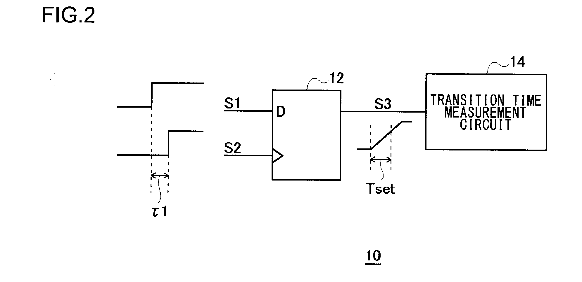
FIG. 2 is a block diagram which shows a configuration of a time measurement circuit 10 according to an embodiment. The time measurement circuit 10 receives a first signal S1 and a second signal S2, and has a function of measuring the time difference (phase difference) between the edges of these two signals. The time measurement circuit 10 includes a sampling circuit 12 and a transition time measurement circuit 14.

T...


PUM


Abstract

A time measurement circuit measures the time difference between edges of a first signal and a second signal. A sampling circuit acquires the logical level of the first signal at a timing of the edge of the second signal. When a sampling circuit enters a metastable state, an output signal thereof transits with a long time scale. A transition time measurement circuit measures a transition time (settling time) of the output signal of the sampling circuit in the metastable state.

Description

BACKGROUND OF THE INVENTION1. Field of the InventionThe present invention relates to a time measurement technique.2. Description of the Related ArtTime to digital converters (which will be referred to as “TDCs” hereafter) are known that are configured to convert the time difference in transition timing between a first signal (which will be referred to as the “start signal” hereafter) and a second signal (the “stop signal”) into a digital value. A method employing a vernier delay circuit has been proposed as a TDC having high time resolution.FIG. 1 is a diagram which shows a configuration of a TDC 300 employing a vernier delay circuit 200. The TDC 300 includes the vernier delay circuit 200 and a priority encoder 100. The vernier delay circuit 200 receives a start signal Sstart and a stop signal Sstop, and generates a thermometer code TC in which the bits change at a particular bit position that corresponds to the time difference between these two signals. The vernier delay circuit 20...

Claims


Application Information

Patent Timeline
Patent Type & Authority Applications(United States)
IPC IPC(8): H03M1/50H03H11/26G01R13/34G04F10/00
CPCG01R31/31709G04F10/005H03K2005/00234H03K5/135H03K5/15026G04F10/10G04F10/00G01R13/34
Inventor YAMAMOTO, KAZUHIROOKAYASU, TOSHIYUKI
Owner ADVANTEST CORP
Why Eureka
Try Eureka