Circularly-Polarized Antenna

a circularly polarized antenna and antenna technology, applied in the direction of polarised antenna unit combinations, electrically long antennas, antennas, etc., can solve the problems of poor voltage standing wave ratio (vswr), large cost, narrow bandwidth capability, etc., and achieve high broadcast transmitter power, broad bandwidth capability, and reduced cost

Inactive Publication Date: 2011-06-09
SPX CORP
View PDF10 Cites 36 Cited by
  • Summary
  • Abstract
  • Description
  • Claims
  • Application Information

AI Technical Summary

Benefits of technology

[0008]Embodiments of the present invention advantageously provide a circularly-polarized antenna that affords pattern versatility, reduced cost, broad bandwidth capability, and support for high broadcast transmitter power, low wind loading, and strong circular polarization.

Problems solved by technology

Deficiencies in existing antenna designs for several broadcasting bands, including the 1.4 GHz band, may include excessive cost, narrow bandwidth capability (i.e., poor voltage standing wave ratio (VSWR), failure to extend over an entire allotted band, or even a substantial fraction thereof), lack of support for high broadcast transmitter power, variable and high wind load, and limited ability to provide circular polarization.
These styles can be so demanding to manufacture as to result in high cost for the achieved performance.

Method used


Image

  • Circularly-Polarized Antenna
  • Circularly-Polarized Antenna
  • Circularly-Polarized Antenna

Examples


Embodiment Construction

[0023]The invention will now be described with reference to the drawing figures, in which like reference numerals refer to like parts throughout.

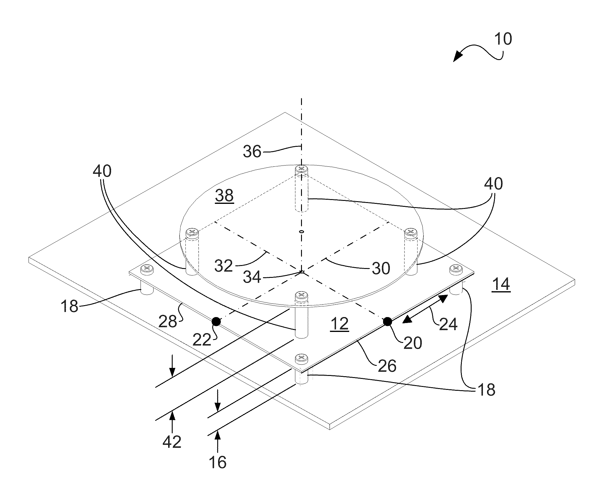
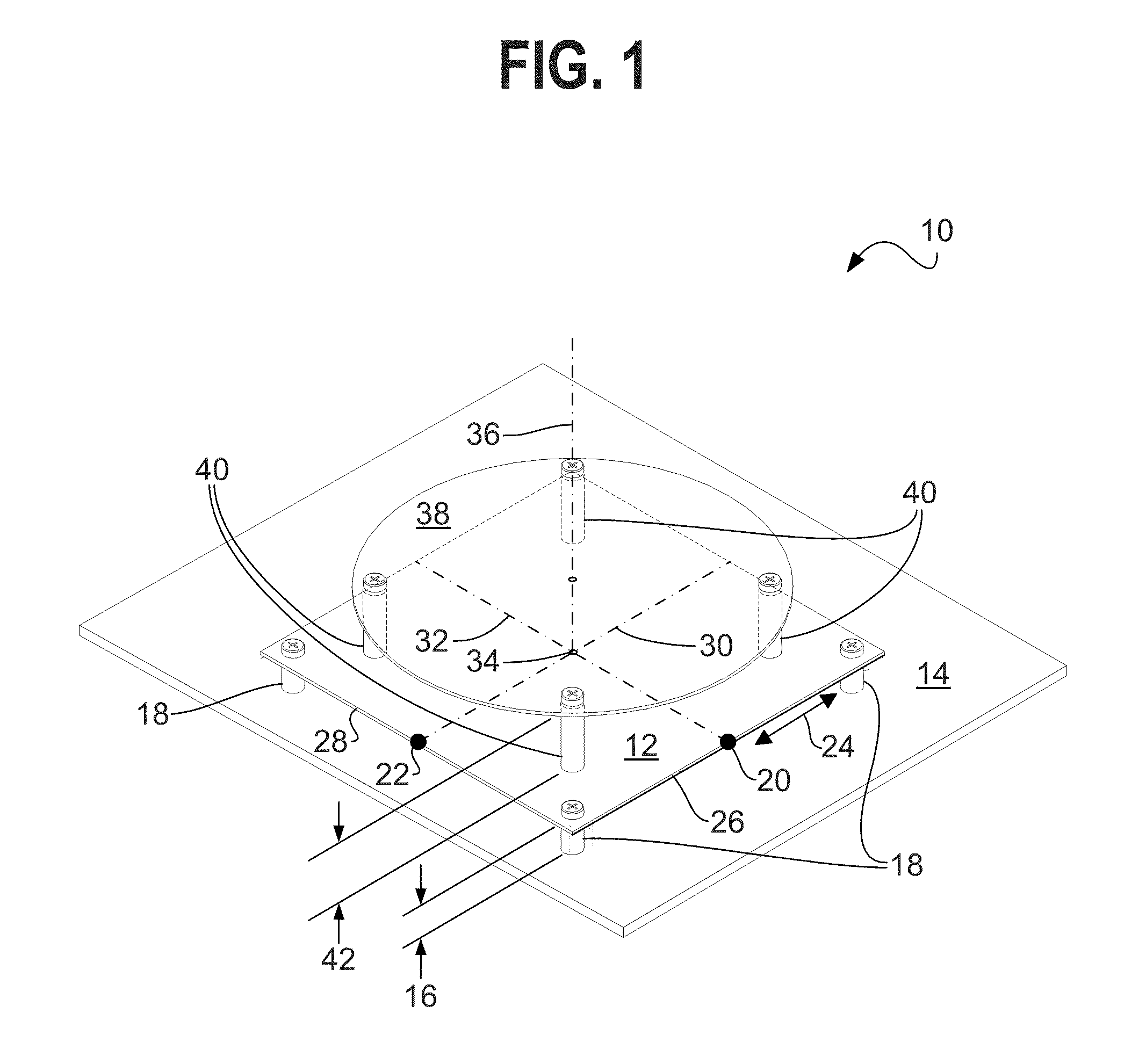
[0024]FIG. 1 is a perspective view of a single radiator 10 according to an embodiment that incorporates the invention. The directly-excited patch component 12 is shown positioned above and parallel to a segment of a backplane 14, by a patch height 16, using insulating standoffs 18 made from a material such as polytetrafluoroethylene (PTFE), polyethylene, or the like. For clarity, placement of the standoffs 18 (incorporating either nonmetallic screws as shown in FIG. 1 or other retention devices such as the barb clips shown in FIG. 4) is displaced from placement of corresponding fittings in succeeding figures, rather than being aligned with the standoffs for the parasitic, discussed below.

[0025]The patch component 12 is excited at nodes 20, 22 on the periphery 24 of the patch 12, at the midpoints of two orthogonal edges 26, 28, on two axes 3...


PUM


Abstract

A circularly-polarized antenna is provided, and includes a conductive backplane with a plurality of panels, a vertical array of patch radiators disposed on one of the backplane panels, and a feed stripline disposed on the backplane panel. The backplane panels are vertical, planar, rectangular and form a right prism. The vertical array has a radiator spacing of one wavelength, each radiator has a face and four edges, and each edge has a length of approximately one half wavelength. The feed stripline includes an input coupled to a coaxial feed cable, and a pair of outputs, orthogonal in position and phase, coupled to each of the radiators.

Description

CROSS-REFERENCE TO RELATED APPLICATIONS[0001]This application claims priority to U.S. patent application Ser. No. 61 / 183,734, filed on Jun. 3, 2009, the disclosure of which is incorporated herein by reference in its entirety.FIELD OF THE INVENTION[0002]The present invention relates generally to radio frequency (RF) electromagnetic signal broadcasting antennas. More particularly, the present invention relates to a circularly-polarized antenna for broadcasting.BACKGROUND OF THE INVENTION[0003]Low-cost mobile handheld devices require stable and clear entertainment video and audio reception, as well as high digital data rates. Circular polarization of broadcast signals reduces dependence on receiving antenna orientation for received signal strength, so that a simple dipole in virtually any orientation, for example, can receive a usable signal.[0004]As in other broadcasting, it can be desirable to achieve particular extents of signal reception range, and to employ a small number of minim...

Claims


Application Information

Patent Timeline
Patent Type & Authority Applications(United States)
IPC IPC(8): H01Q21/08H01Q19/00
CPCH01Q9/0428H01Q9/0435H01Q21/24H01Q21/08H01Q21/065
Inventor SCHADLER, JOHN L.SKALINA, ANDRE
Owner SPX CORP
Why Eureka
Try Eureka