
Module for use in mobile communication terminal and mobile communication terminal applying the same therein

module technology, applied in the field of modules for mobile communication terminals and mobile communication terminals applying the same therein, can solve the problems of increasing power consumption, noise leakage from a transmitting system to a receiving system affecting the receiving characteristics of a mobile communication terminal, and no particular consideration is given, so as to achieve small size and high reliability

Inactive Publication Date: 2011-06-09
HITACHI MEDIA ELECTORONICS CO LTD
View PDF8 Cites 45 Cited by
  • Summary
  • Abstract
  • Description
  • Claims
  • Application Information

AI Technical Summary

Benefits of technology

"The present invention provides a module for a mobile communication terminal that can simultaneously transmit and receive signals using different frequency bands. The module includes a filter with variable characteristics that separates transmission and reception signals, and a jamming signal cancel portion that cancels out transmission signals and noises of the reception band. The invention also provides a small-sized and reliable module that can be used with multiple frequency bands, and a mobile communication terminal that utilizes the same. Additionally, the invention helps to minimize power consumption and improve the receiving characteristics of the mobile communication terminal."

Problems solved by technology

Also, no particular consideration is paid upon, also about a power consumption of the feed forward loop.
However, if constructing the DPX with a variable filter, because a degree of suppression of a high-level transmission signal on the transmitter side and / or a degree of suppression of reception band noises on the transmitter side are / is lowered down, it comes up to be a problem that noises leaking from a transmitting system to a receiving system affect ill influences upon the receiving characteristics of a mobile communication terminal.
Further, in such case, it is also a problem to suppress an increase of the power consumption down to the minimum.

Method used


Image

  • Module for use in mobile communication terminal and mobile communication terminal applying the same therein
  • Module for use in mobile communication terminal and mobile communication terminal applying the same therein
  • Module for use in mobile communication terminal and mobile communication terminal applying the same therein

Examples


embodiment 2

[0044]FIG. 9 is a block diagram for showing an example of the structure of a module for use in the mobile communication terminal, according to a second embodiment. Herein, in the place of the variable DPX 2 according to the embodiment 1 is used a circulator 36. Since other components than that are same to those of the embodiment 1, explanation thereof will be omitted. The circulator is a device for obtaining isolation between terminals with using a physical phenomenon, such as, a Faraday rotation, etc., for example, and wherein, signals can pass through between terminals 25 and 26 and terminals 26 and 27 of the circulator 36, without attenuation thereof, and therefore, it is possible to make the signal leakage small, from the transmission system to the reception system, covering over a relatively wide band, by bringing the isolation between the terminals 25 and 27.

[0045]FIG. 10 is a view for showing the isolation characteristics between the transmission system and the reception syst...

embodiment 3

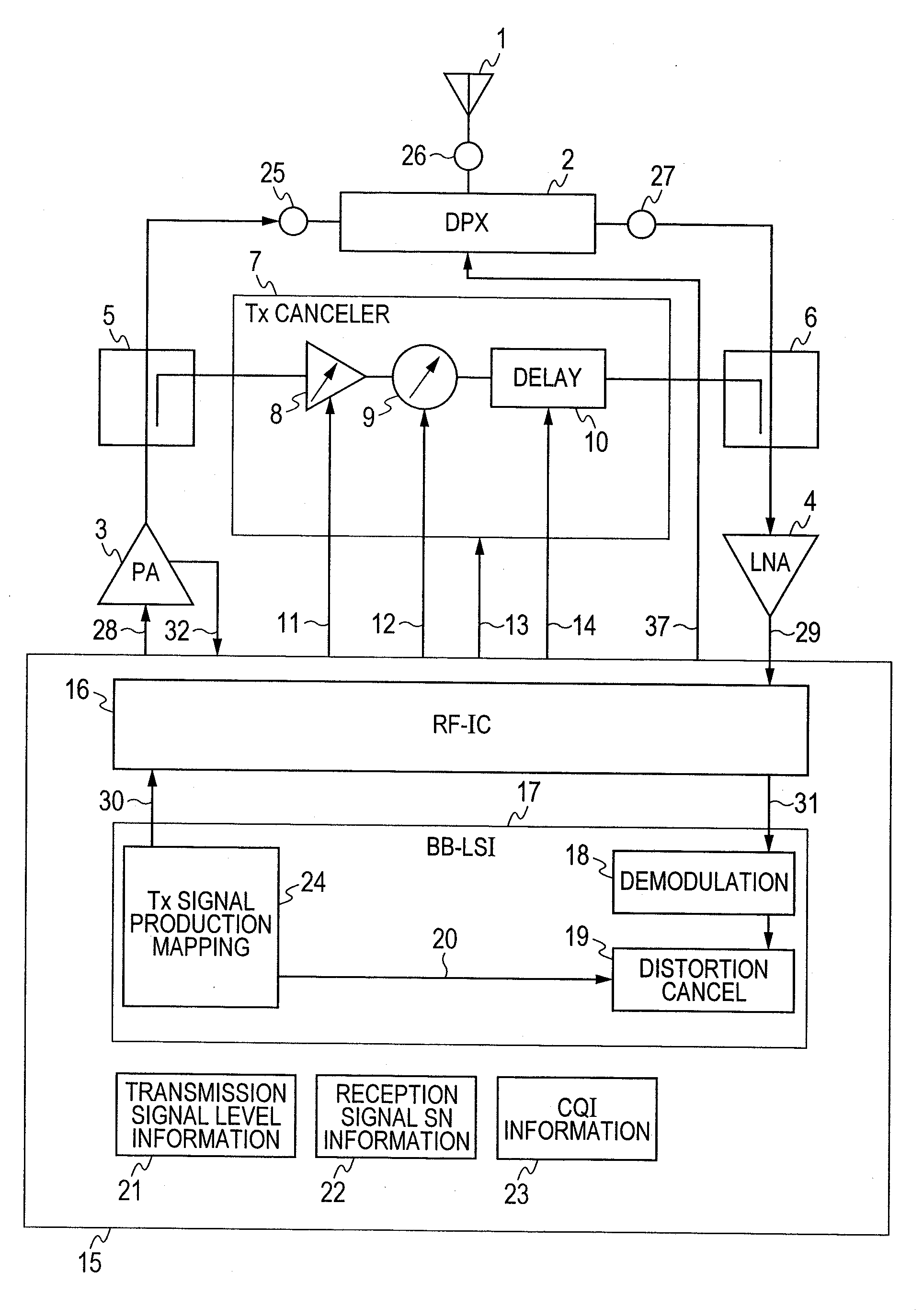
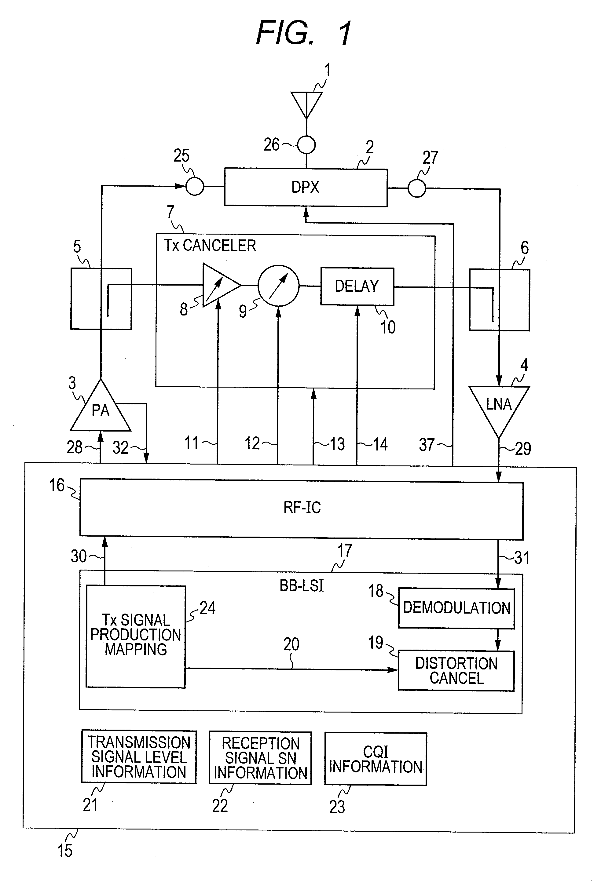
[0048]FIG. 11 is a block diagram for showing an example of the structure of a module for use in the mobile communication terminal, according to a third embodiment. In this FIG. 11, a jamming wave cancel within the front-end portion is inputted from the coupler is build up by a feed forward loop, which is constructed with the distributor 5, the jamming wave canceller 7 and a composer 6. The transmission signal 28 to an input of the PA 3, after being distributed within the distributor 5, is inputted to the jamming wave canceller 7. The composer 6 composes an output of the jamming wave canceller 7 and an output of the DPX 2, thereby to input it to the LNA 4. There can be obtained an effect similar to that of the embodiment 1 shown in FIG. 1, i.e., distributing it from the output of the PA 3 and inputting it to the jamming wave canceller 7.

[0049]FIG. 12 is a block diagram for showing an example of applying the module according to the present invention into a multi-band enable mobile com...


PUM


Abstract

For providing a module for use of a mobile communication terminal, being small in sizes and high in reliability, and enabling with plural numbers of bands, and also a mobile communication terminal with using the same therein, canceling is conducted on transmission signal and / or noises of reception band on reception side with using a feed forward technology, for maintaining a degree of suppression of the transmission signal and / or the noises of reception band on the reception side. In this case, for achieving the cancellation of wide band signals from the transmission signal to the reception band, a delay adjusting function is used, in addition to gain and phase adjusting functions. Also, for conducting stable canceling of jamming signals, controls are conducted on the gain, the phase and the delay of a loop with using a reception SN and / or a CQI signal, etc.Further, for achieving low power consumption, a feed forward loop can be made ON / OFF depending on a level of the transmission signal.

Description

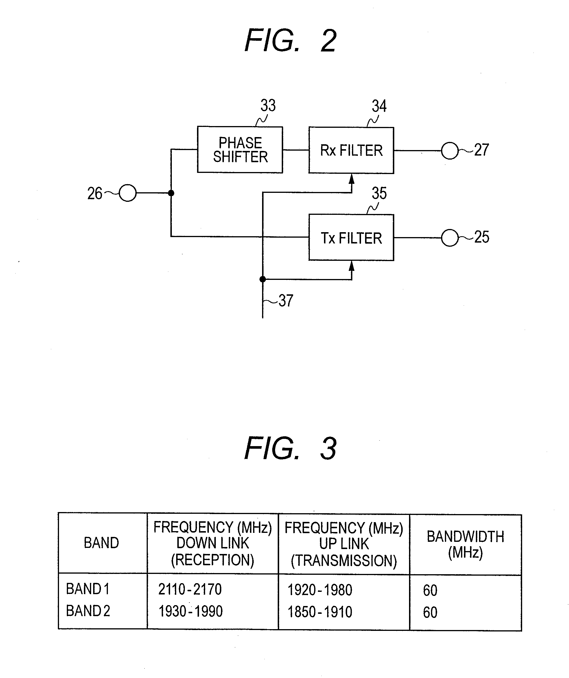
[0001]This application relates to and claims priority from Japanese Patent Application No. 2009-277142 filed on Dec. 7, 2009, the entire disclosure of which is incorporated herein by reference.BACKGROUND OF THE INVENTION[0002]The present invention relates to a module for use in a mobile communication terminal and a mobile communication terminal applying the same therein. And, in particular, it relates to the module for use in a mobile communication terminal, being compatible with a wireless communication system, such as, a WCDMA method or a LTE method, etc., for example, and the mobile communication terminal applying the same therein.[0003]For a mobile phone, various studies are made on new methods, such as, the LTE method, etc., other than the WCDMA method, which was already put in a practical use thereof. With the WCDMA method and the LTE method, because of simultaneous operation of transmission and reception, they operate in different bands of frequencies, when transmitting and w...

Claims


Application Information

Patent Timeline
Patent Type & Authority Applications(United States)
IPC IPC(8): H04B7/005
CPCH04L5/143H04L2025/03573H04L2025/03503H04L5/1461
Inventor YAMAMOTO, AKIOAKIYAMA, HITOSHISHIBA, TAKASHIHIKINO, OSAMU
Owner HITACHI MEDIA ELECTORONICS CO LTD
Learn More