
Communication system, terminal device, base station, communication quality management method, and program

a communication quality management and terminal device technology, applied in the field of communication systems, can solve the problems of reducing the support of the complete same qos between the two networks, the inability of the operator managing the source network to direct manage the qos of the non-3gpp network (target network), and the inability to perform direct access from the base station of the 3gpp network to the terminal device, etc., to achieve the effect of suppressing the reduction of communication quality

Inactive Publication Date: 2011-06-09
PANASONIC CORP
View PDF6 Cites 62 Cited by
  • Summary
  • Abstract
  • Description
  • Claims
  • Application Information

AI Technical Summary

Benefits of technology

[0013]The present invention has been made in consideration of the background described above. An object of the present invention is to provide a communicat

Problems solved by technology

However, in conventional systems, the same QoS (Quality of Service) system is not necessarily adopted by different RATS between which a terminal device moves.
In this case, even if QoS support is provided under a roaming agreement between a 3GPP network and a non-3GPP network, the completely same QoS may not necessarily be supported by the two networks due to differences in QoS systems and the like.
Therefore, after a handover from the 3GPP network to the non-3GPP network takes place, an operator managing the 3GPP network (source network) can no longer directly manage the QoS of the non-3GPP network (target network).
In other words, direct access can no longer be performed from a base station of the 3GPP network to a terminal device.
Therefore, the 3GPP network (source network) cannot grasp the QoS state of the non-3GPP network by directly issuing a measurement instruction to a terminal or receiving a report therefrom.
With such conventional systems, the service quality (QoS) of a target network may decline when a terminal device moves from a 3GPP network to a non-3GPP network.
For example, even when the QoS of the target network (non-3GPP network) is adjusted in advance with the target network, since the completely same QoS is not supported, there may be cases where the service quality (QoS) of the target network after an actual handover turns out to be low.
As a result, there is a risk that the reduction in QoS may affect a plurality of terminal devices instead of just one terminal device.

Method used


Image

  • Communication system, terminal device, base station, communication quality management method, and program
  • Communication system, terminal device, base station, communication quality management method, and program
  • Communication system, terminal device, base station, communication quality management method, and program

Examples


first embodiment

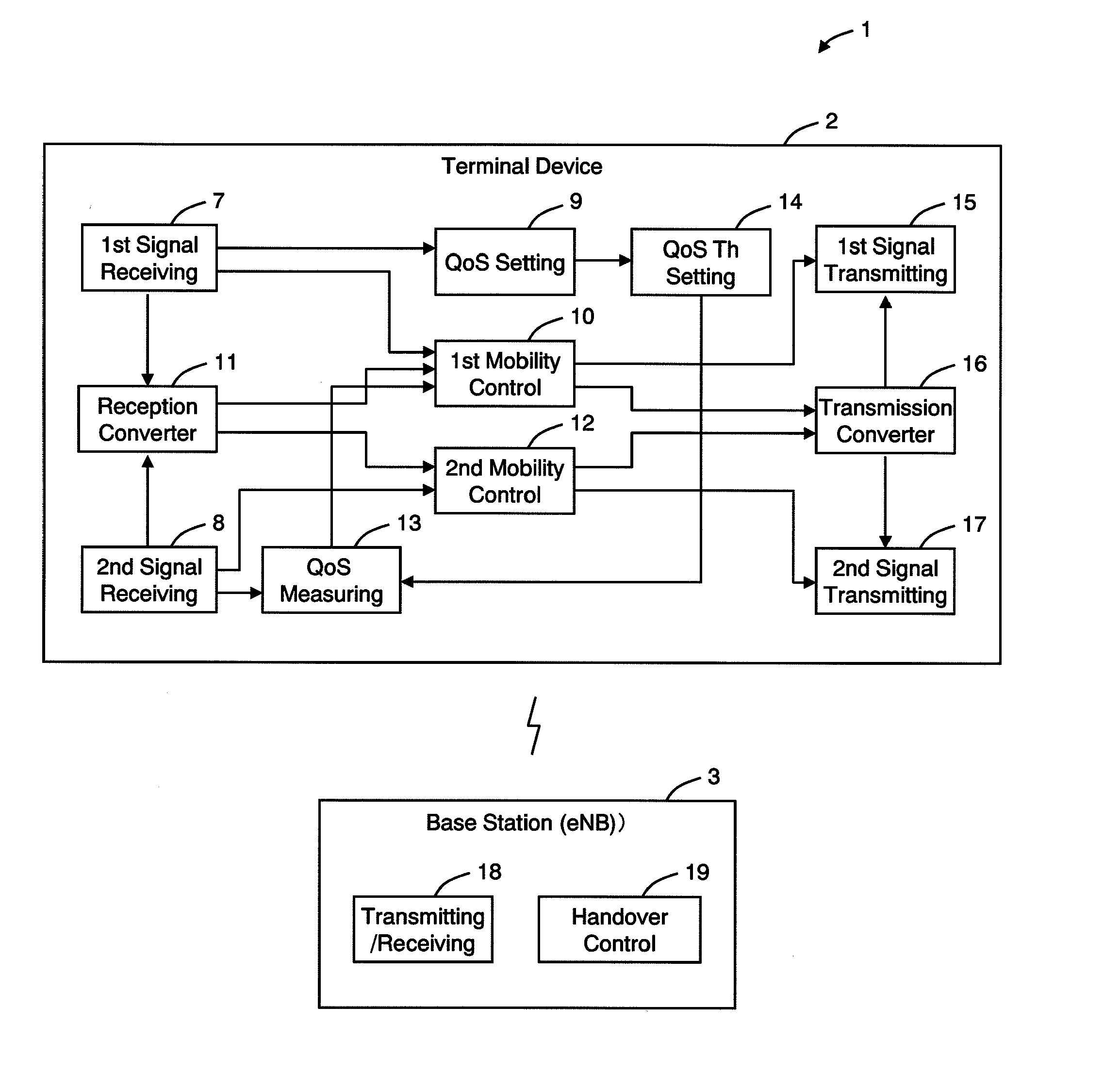
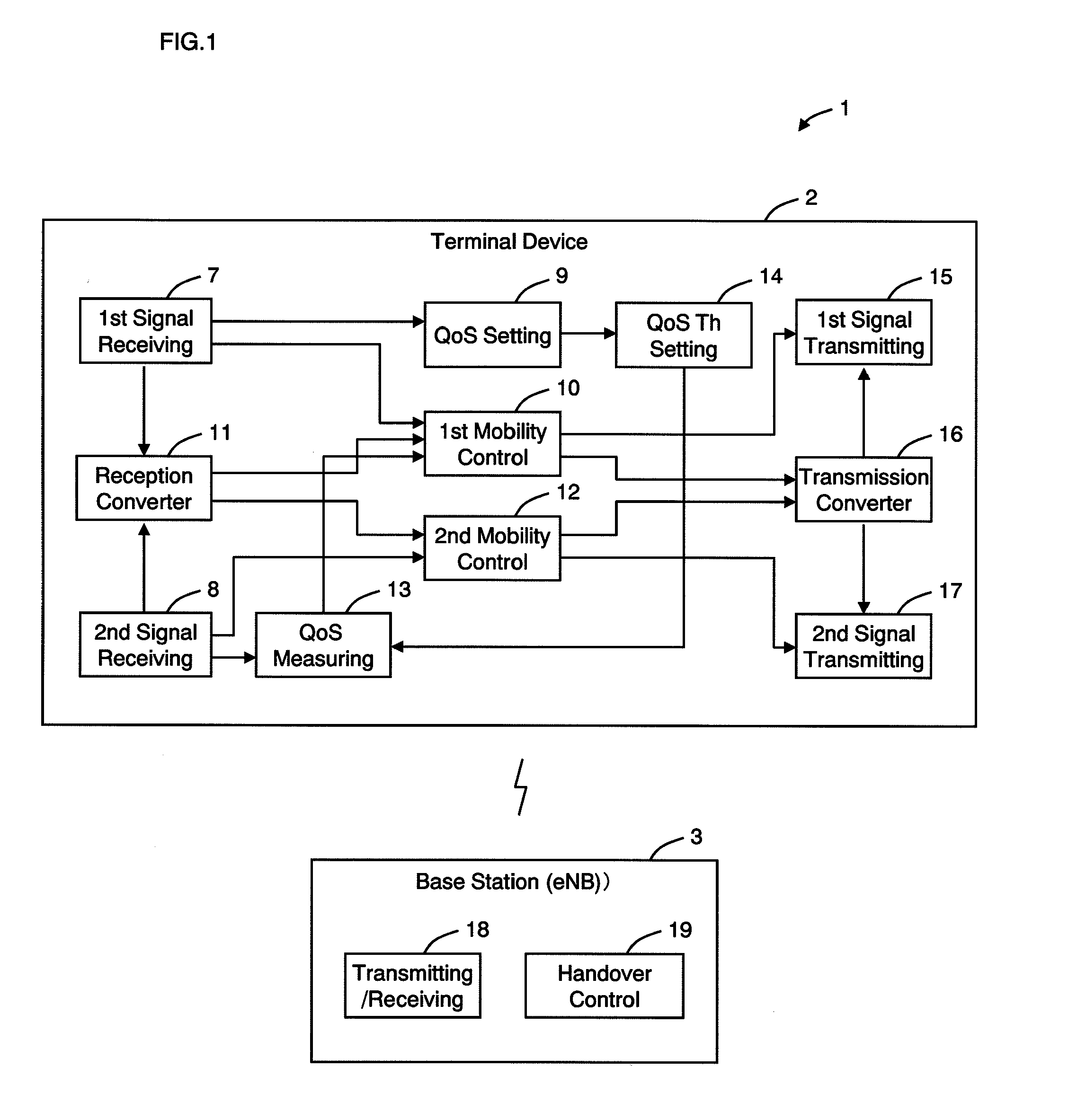
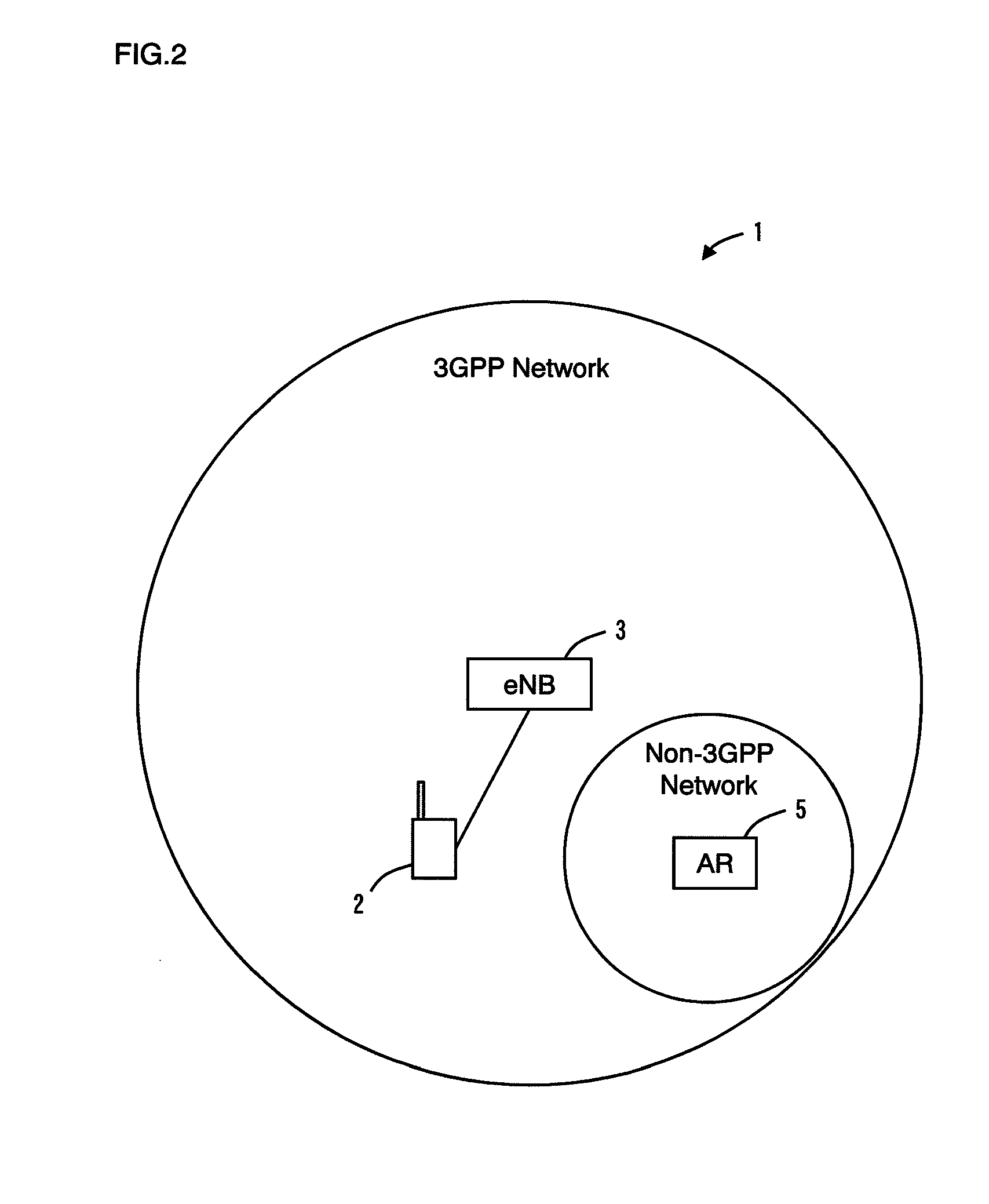
[0112]A communication system according to a first embodiment of the present invention will now be described with reference to FIGS. 1 to 6. FIG. 1 is a block diagram illustrating configurations of a terminal device and a base station used in a communication system according to the present embodiment. FIG. 2 is an explanatory diagram of communication areas of a 3GPP network and a non-3GPP network. First, a network environment of a communication system according to the present embodiment will be described with reference to FIG. 2.

[0113]As illustrated in FIG. 2, in a communication system 1 according to the present embodiment, a communication area of a 3GPP network is wider than a communication area of a non-3GPP network. The communication area of the non-3GPP network is contained in the communication area of the 3GPP network. In addition, different communication protocols are respectively used in the 3GPP network and the non-3GPP network. In this case, the 3GPP network corresponds to a...

second embodiment

[0162]Next, a communication system 1 according to a second embodiment of the present invention will now be described with reference to FIGS. 7 to 9. Here, points in which the communication system 1 according to the present embodiment differs from the first embodiment will be primarily described. As such, unless particular reference is made, configurations and operations according to the present embodiment are the same as those of the first embodiment.

[0163]The present embodiment differs from the first embodiment in that QoS threshold information is not included in QoS control information to be sent from a first signal receiving unit 7 to a QoS setting unit 9 and is instead included in mobility control information of a 3GPP network to be sent from the first signal receiving unit 7 to a first mobility control unit 10.

[0164]FIG. 7 is a block diagram illustrating configurations of a terminal device 2 and a base station used in the communication system 1 according to the present embodime...

third embodiment

[0185]Next, a communication system according to a third embodiment of the present invention will now be described with reference to FIGS. 12 to 14. While the first and second embodiments are characterized by operations performed when a terminal device is in communication (also referred to as call connected, an active state, or when connected to an LTE system, referred to as an RRC_CONNECTED state), the present embodiment is characterized by operations when a terminal device is on standby (also referred to as an idle state, or when connected to an LTE system, referred to as an RRC_IDLE state). Hereafter, a communication system according to the present embodiment will be described, with a focus on such characteristics (points in which the present embodiment differs from the first and second embodiments).

[0186]First, with reference to FIG. 12, configurations of a terminal device 101 and a base station 102 used in a communication system 100 according to the present embodiment will be de...


PUM


Abstract

In a communication system (1), a handover of a terminal device (2) is performed between a base station (eNB (3)) of a 3GPP network and a base station (AR (5)) of a non-3GPP network, a QoS measurement result of the handover target network (non-3GPP network) is reported via an interface (ePDG (6)) provided between the 3GPP network and the non-3GPP network, with the base station (AR (5)) of the non-3GPP network acting as a relay, to the base station (eNB (3)) of the 3GPP network, and the handover to the non-3GPP network is controlled according to the QoS measurement result. Accordingly, a communication system can be provided which is capable of suppressing a reduction in communication quality when a handover is performed between networks with different communication protocols.

Description

TECHNICAL FIELD[0001]The present invention is related to a communication system including a function for suppressing a reduction in communication quality when a handover is performed between networks with different communication protocols.BACKGROUND ART[0002]One of the key objectives of LTE (Long Term Evolution) / SAE (System Architecture Evolution) currently under standardization by 3GPP is to be able to accommodate a plurality of RATs (Radio Access Technologies) (refer to Non-Patent Documents 1 and 2). RATs include UTRAN, GERAN, E-UTRAN, WLAN 3GPP access systems, non-3GPP access systems, and the like. Various communication protocols are used in the respective networks. The plurality of RATs respectively have different characteristics (coverage, transmission rate, introduction / operation costs, and the like). For example, such techniques are disclosed in 3GPP TR23.882 V1.12.0, “3GPP System Architecture Evolution (SAE): Report on Technical Options and Conclusions” and in 3GPP TS36.300 ...

Claims


Application Information

Patent Timeline
IPC IPC(8): H04W36/00
CPCH04W36/26H04W36/0066
Inventor AOYAMA, TAKAHISAHIRANO, JUN
Owner PANASONIC CORP
Features
  • Generate Ideas
  • Intellectual Property
  • Life Sciences
  • Materials
  • Tech Scout
  • Unparalleled Data Quality
  • Higher Quality Content
  • 60% Fewer Hallucinations
Learn More