Stop line recognition device

a recognition device and stop line technology, applied in road vehicle traffic control, instruments, computing, etc., can solve the problems of reducing the recognition accuracy of stop lines, long processing time of driving support control itself and the like, and high accuracy, and generating excessive calculation load

Active Publication Date: 2011-06-09
SUBARU CORP
View PDF44 Cites 26 Cited by
  • Summary
  • Abstract
  • Description
  • Claims
  • Application Information

AI Technical Summary

Benefits of technology

[0011]According to an aspect of the present invention, the stop line recognition device can recognize a stop line tha

Problems solved by technology

Therefore, if the recognition of the stop line is constantly performed at a level similar to a level for the preceding vehicle, traffic signal and the like, unnecessary calculation load may be increased, which may result in a very longer processing time of driving support control itself and the like.
Furthermore, for ex

Method used


Image

  • Stop line recognition device
  • Stop line recognition device
  • Stop line recognition device

Examples


Embodiment Construction

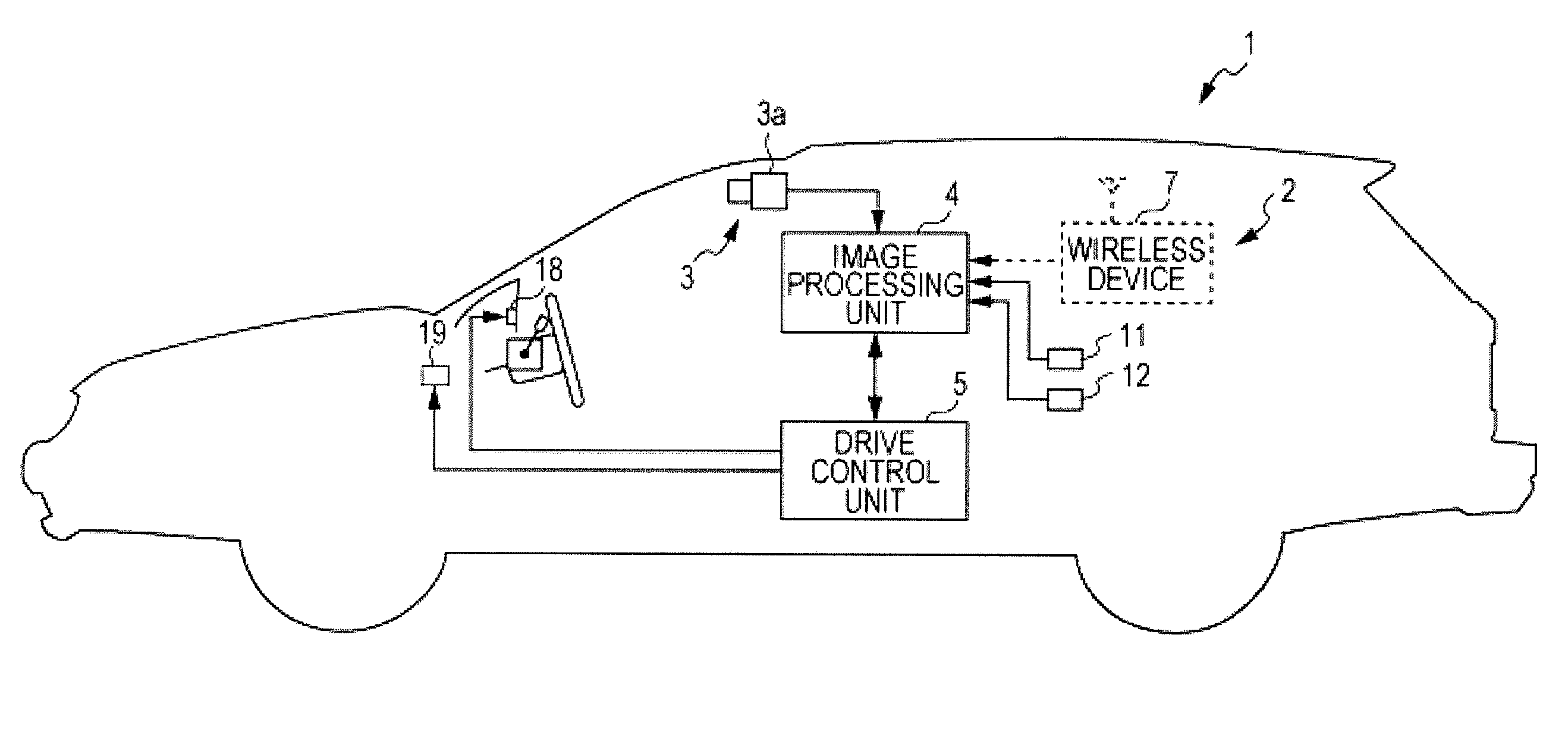
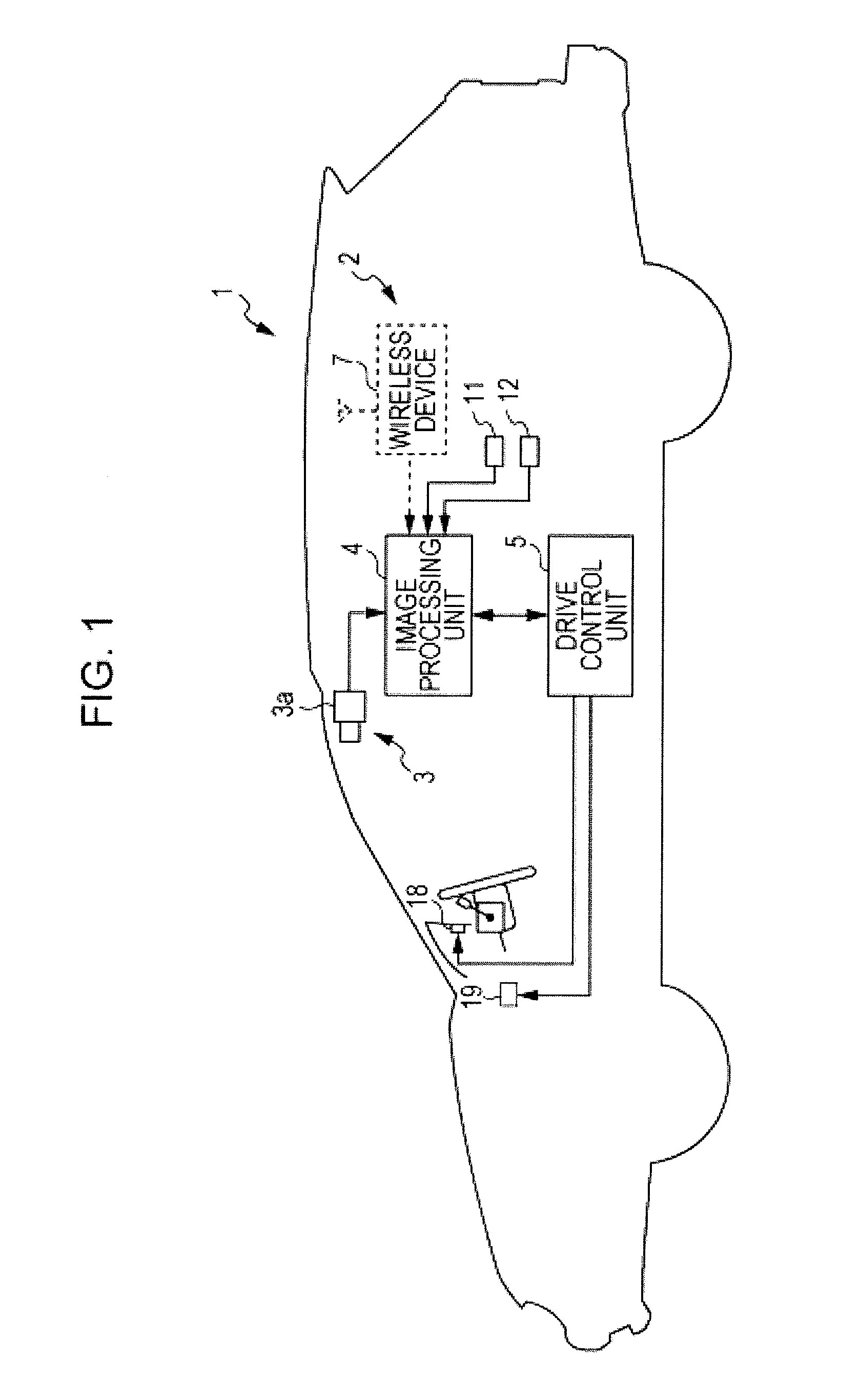
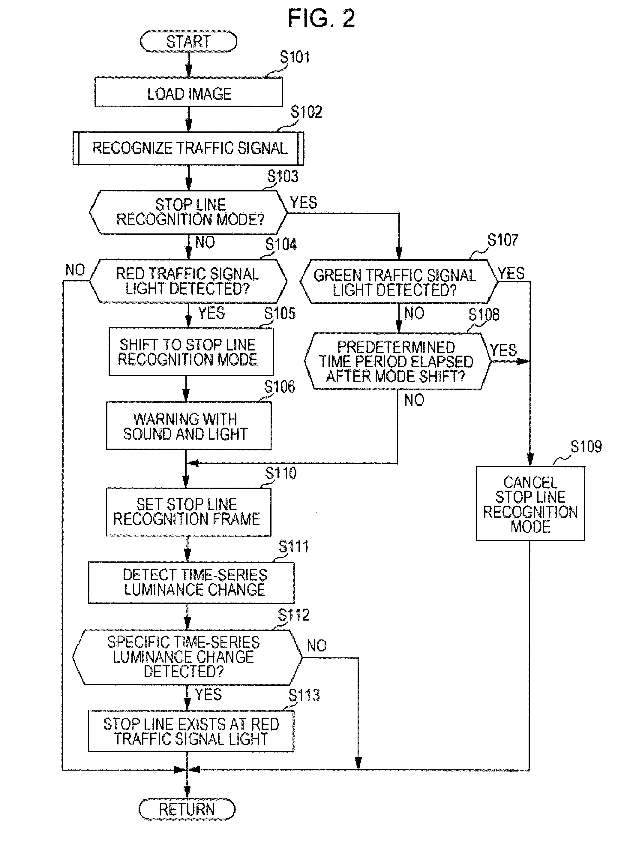
[0019]Embodiments of the present invention will hereunder be described with reference to the drawings. FIGS. 1 to 5 relate to a stop line recognition device according to a first embodiment of the present invention: FIG. 1 is a schematic block diagram of the stop line recognition device; FIG. 2 is a flowchart showing a stop line recognition routine; FIG. 3 is a flowchart showing a traffic signal recognition subroutine; FIG. 4 is an illustrative view showing a traffic signal recognition frame and a stop line recognition frame; FIG. 5 is an illustrative view showing an example of the stop line recognition frame that is set on an image.

[0020]In FIG. 1, a stop line recognition device 2 installed on a vehicle such as an automobile (own vehicle) 1 is mainly composed of an image capturing optical system 3, an image processing unit 4 and a drive control unit 5.

[0021]The image capturing optical system 3 is, for example, mainly composed of a monocular camera 3a that is mounted in a front ceili...


PUM


Abstract

An image processing unit 4 performs the recognition of a traffic signal in front of an own vehicle on the carriageway thereof. When the image processing unit 4 recognizes that there is a traffic signal front closet to the vehicle on the carriageway within a set distance L2 and the traffic signal is displaying red light, the process shifts to a stop line recognition mode and the image processing unit 4 performs stop line recognition. Accordingly, unnecessary execution of stop line recognition can be accurately avoided. Therefore, a stop line that is necessary for the control of the own vehicle can be recognized with a high accuracy without generating excessive calculation load.

Description

CROSS REFERENCES TO RELATED APPLICATIONS[0001]The present application claims priority from Japanese Patent Application No. 2009-279753 filed on Dec. 9, 2009, the entire contents of which are hereby incorporated by referenceBACKGROUND OF THE INVENTION[0002]1. Field of the Invention[0003]The present invention relates to stop line recognition devices that recognize a stop line in front of the carriageway of a vehicle.[0004]2. Description of the Related Art[0005]In recent years, various driving support systems for vehicles have been under development as part of efforts of the Intelligent Transport System (ITS). For example, Japanese Unexamined Patent Application Publication No. 2005-170154 (hereunder referred to as “Patent Document 1”) discloses a technology that performs image recognition such as template matching to an image signal captured by a charge-coupled device (CCD) camera to extract a specific object that indicates that an own vehicle should stop, and performs driving support ...

Claims


Application Information

Patent Timeline
IPC IPC(8): G06K9/00G06V10/22
CPCG06K9/2054G08G1/0962G06K9/00825G06K9/00798G08G1/09623G06V20/584G06V20/588G06V10/22
Inventor KUDO, SHINYA
Owner SUBARU CORP
Why Eureka
Try Eureka