Cutting Insert, Cutting Tool, and Method of Cutting Workpiece Using the Same

a cutting tool and cutting insert technology, applied in the direction of shaping cutters, manufacturing tools, transportation and packaging, etc., can solve the problems of poor fracture resistance and thickness of cutting inserts, and achieve the effect of excellent fracture resistance, low cutting resistance and equal or lower cutting resistan

Active Publication Date: 2011-06-09
KYOCERA CORP
View PDF33 Cites 43 Cited by
  • Summary
  • Abstract
  • Description
  • Claims
  • Application Information

AI Technical Summary

Benefits of technology

[0005]An advantage of the invention is to provide the cutting insert and the cutting tool which exhibit a low cutting resistance and excellent fracture resistance, as well as the method of cutting a workpiece using the same.
[0006]A cutting insert according to an embodiment of the present invention includes an upper face; a lower face; a side face which is located between the upper face and the lower face and includes at least one upper concave portion extending along a thickness direction up to the upper face; and a plurality of divided upper cutting edges which are located at an intersection of the upper face and the side face and are divided by the at least one upper concave portion. Each of the plurality of divided upper cutting edges includes first end located at one end and a second end located at the other end, and is inclined being closer to the lower face from the first end toward the second end when viewed from side. The plurality of divided upper cutting edges include a first divided upper cutting edge and a second divided upper cutting edge adjacent to the second end of the first divided upper cutting edge through the at least one upper concave portion. When viewed from side, the first end of the second divided upper cutting edge is located above an intersection of an extension line extended from the first divided upper cutting edge toward the second divided upper cutting edge, and a line which passes through the first end of the second divided upper cutting edge and is parallel to the central axis of the cutting insert. When viewed from side, the first end of the second divided upper cutting edge is located at the same position as the second end of the first divided upper cutting edge or is located below the second end of the first divided upper cutting edge.
[0007]A cutting tool according to an embodiment of the present invention includes the cutting insert; and a holder to which the cutting insert is attached.
[0008]A cutting tool according to other embodiment of the present invention includes the plurality of cutting inserts; and a holder to which the plurality of cutting inserts are attached. Two of a plurality of the cutting inserts are attached to the holder with their respective upper faces and their respective lower faces positioned oppositely.
[0009]A method of cutting a workpiece according to an embodiment of the present invention includes: rotating the cutting tool around the central axis of the holder; bringing at least one of the plurality of divided upper cutting edges or at least one of the plurality of divided lower cutting edges of the rotating cutting tool into contact with a surface of the workpiece; and separating the cutting tool relatively from the workpiece.
[0010]The insert according to the embodiment of the present invention includes the upper concave portion, and is arranged so that the plurality of divided upper cutting edges divided by the upper concave portion are inclined being closer to the lower face from the first end toward the second end. Therefore, this insert achieves a cutting resistance equal to or lower than that of a conventional insert including a cutting edge inclined linearly along a longitudinal direction. When viewed from side, the first end of the second divided upper cutting edge is located at the same position as the second end of the first divided upper cutting edge or is located therebelow. Therefore, when a workplace is cut by attaching the insert to the holder, the first divided upper cutting edge and the second divided upper cutting edge can be applied sequentially to the workpiece, thereby further decreasing the cutting resistance. Additionally, when viewed from side, the first end of the second divided upper cutting edge is located above the intersection of the extension line extending from the first divided upper cutting edge toward the second divided upper cutting edge and the line which passes through the first end of the second divided upper cutting edge and is parallel to the central axis of the cutting insert. Therefore, in the insert including the plurality of divided upper cutting edges inclined as described above, a relatively large thickness between the upper face and the lower face can be ensured, thereby exhibiting excellent fracture resistance.

Problems solved by technology

However, the disadvantage of poor fracture resistance occurs because the thickness of the cutting insert 20 (the distance between a first end face 28 and a second end face 30) is decreased with increase in inclination of the main edge 46.

Method used


Image

  • Cutting Insert, Cutting Tool, and Method of Cutting Workpiece Using the Same
  • Cutting Insert, Cutting Tool, and Method of Cutting Workpiece Using the Same
  • Cutting Insert, Cutting Tool, and Method of Cutting Workpiece Using the Same

Examples


Embodiment Construction

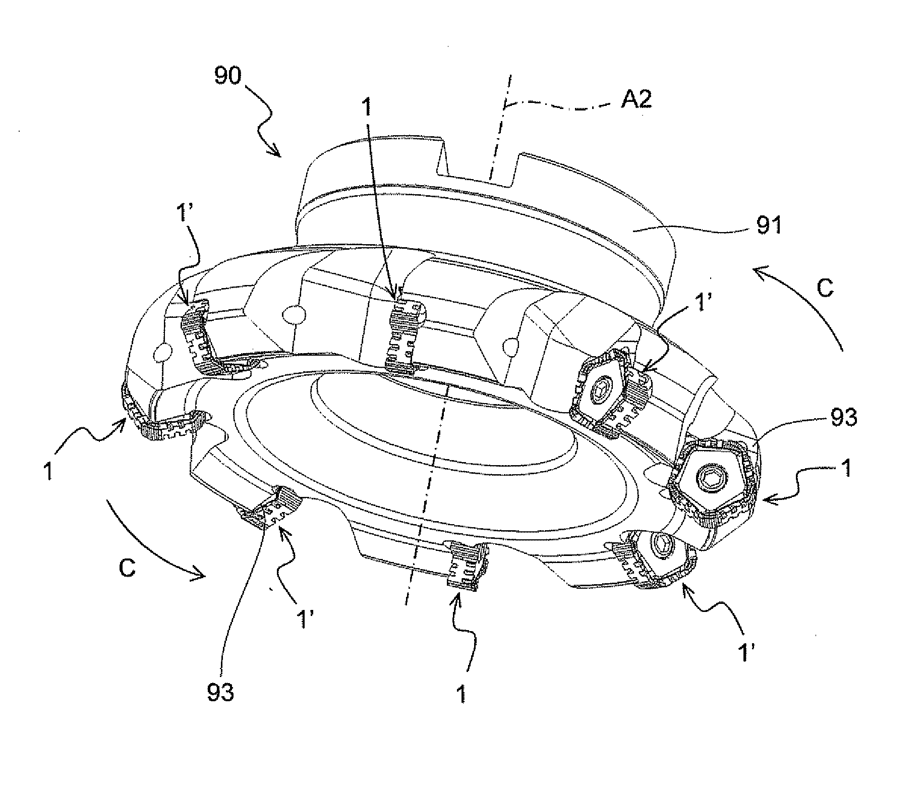
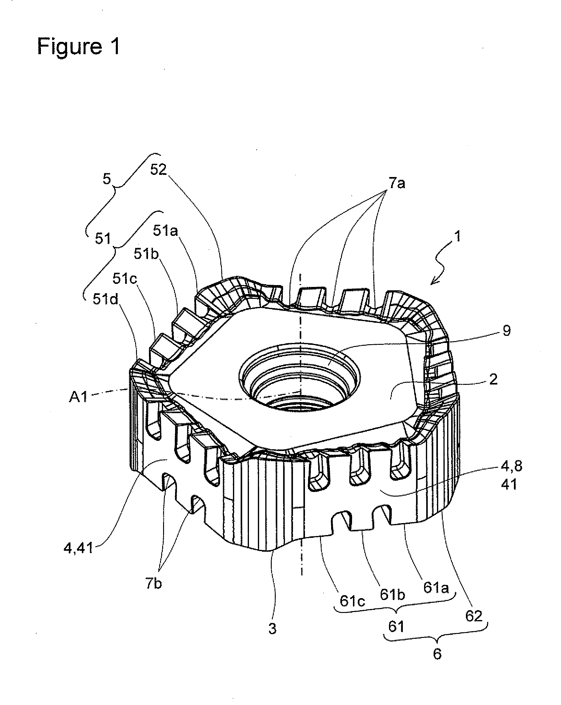
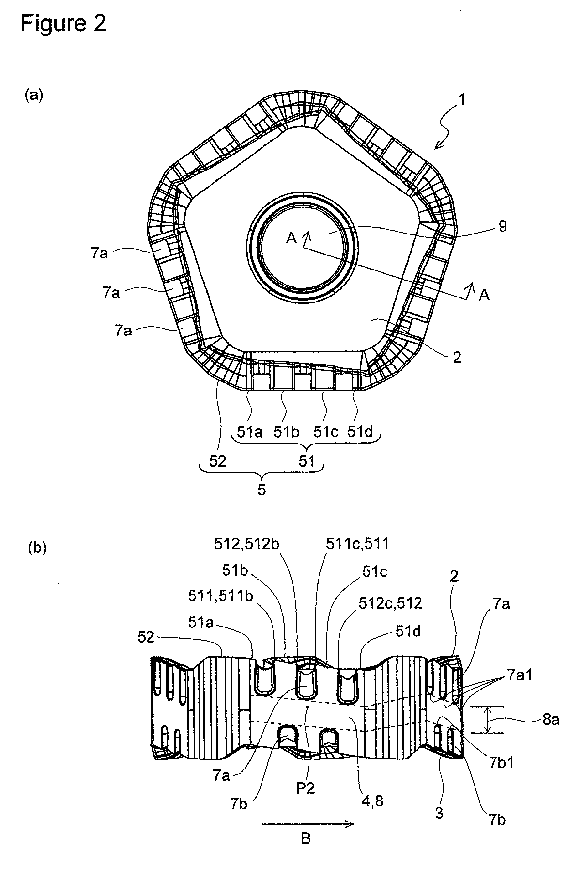
[0023]An embodiment of the cutting insert according to the present invention is described in detail with reference to FIGS. 1 to 5. As shown in FIGS. 1 to 2(b), the cutting insert 1 of the present embodiment includes an upper face 2; a lower face 3; a side face 4 connected to the upper face 2 and the lower face 3; a through hole 9 (attachment hole) extending between the upper face 2 and the lower face 3; an upper cutting edge 5 located along an intersection of the upper face 2 and the side face 4; and a lower cutting edge 6 located along an intersection of the lower face 3 and the side face 4. The side face 4 includes at least an upper concave portion 7a which extends up to the upper face 2 along a thickness direction, and divides the upper cutting edge 5 into a plurality of divided upper cutting edges 51a to 51d; at least a lower concave portion 7b which extends up to the lower face 3 along the thickness direction, and divides the lower cutting edge 6 into a plurality of divided lo...


PUM

PropertyMeasurementUnit
thicknessaaaaaaaaaa
inclination anglesaaaaaaaaaa
widthaaaaaaaaaa

Abstract

A cutting insert of the present invention includes a side face having an upper concave portion which is located between an upper face and a lower face and extends up to the upper face, and a plurality of divided upper cutting edges which are located at the intersection of the upper face and the side face, and are divided by the upper concave portion. Each of these divided upper cutting edges includes a first end and a second end, and is inclined being closer to the lower face from the first end toward the second end. The plurality of divided upper cutting edges include a first divided upper cutting edge and a second divided upper cutting edge adjacent to each other. When viewed from side, the first end of the second divided upper cutting edge is located above the intersection of an extension line of the first divided upper cutting edge, and a line which passes through the first end of the second divided upper cutting edge and is parallel to the central axis of the cutting insert, and is located at the same position as the second end of the first divided upper cutting edge, or located therebelow. A cutting tool including the cutting insert, and a method of cutting a workpiece by using the cutting tool are also provided.

Description

TECHNICAL FIELD[0001]The invention relates to a cutting insert, a cutting tool, and a method of cutting a workpiece using the same.BACKGROUND ART[0002]As a cutting insert (hereinafter referred to as “insert” in some cases), a cutting insert 20 whose main edge 46 is inclined has heretofore been disclosed in, for example, FIG. 4 of Japanese Unexamined Patent Publication No. 2008-544872. It is preferable to incline the main edge 46 from the standpoint of decreasing cutting resistance.[0003]However, the disadvantage of poor fracture resistance occurs because the thickness of the cutting insert 20 (the distance between a first end face 28 and a second end face 30) is decreased with increase in inclination of the main edge 46.[0004]Hence, there is a demand for a cutting insert exhibiting a low cutting resistance and excellent fracture resistance.SUMMARY OF THE INVENTION[0005]An advantage of the invention is to provide the cutting insert and the cutting tool which exhibit a low cutting res...

Claims


Application Information

Patent Timeline
Patent Type & Authority Applications(United States)
IPC IPC(8): B23C5/22B23B27/16B23C5/06
CPCB23C5/06B23C5/202B23C2200/0444B23C2200/128B23C2200/203B23C2200/205Y10T407/1962Y10T407/23Y10T407/2274Y10T407/2272Y10T409/303808Y10T407/1936Y10T407/192B23C2200/326
Inventor KOGA, KENICHIROU
Owner KYOCERA CORP
Why Eureka
Try Eureka