Hay bale stacker

Inactive Publication Date: 2011-06-09
ASHMORE ENG PTY LTD
View PDF17 Cites 4 Cited by
  • Summary
  • Abstract
  • Description
  • Claims
  • Application Information

AI Technical Summary

Benefits of technology

[0007]The aim of the present invention is to provide a hay bale stacker that can follow a hay baler

Problems solved by technology

The weight of such bales varies depending upon its size and composition; however, with modern farming techniques bales are of a considerable weight that makes their handling and transportation problematic at times.
The process of initially lifting the bales on to the vehicle or trailer with a front end loader is often cumbersome and time-consuming.
The latter procedure is particularly dangerous given most hay is loaded at night and vision is compromised.
This acti

Method used


Image

  • Hay bale stacker
  • Hay bale stacker
  • Hay bale stacker

Examples


Embodiment Construction

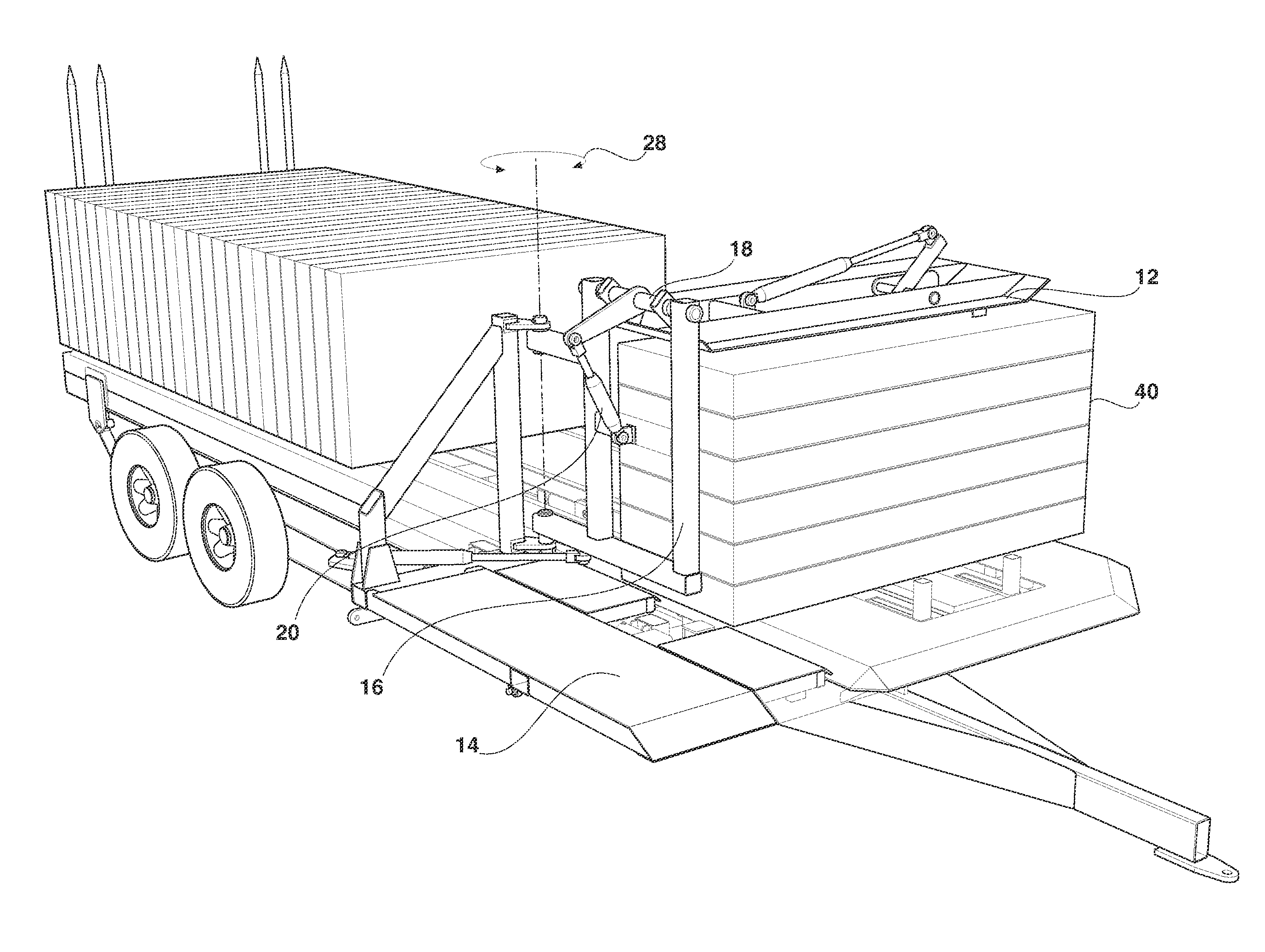
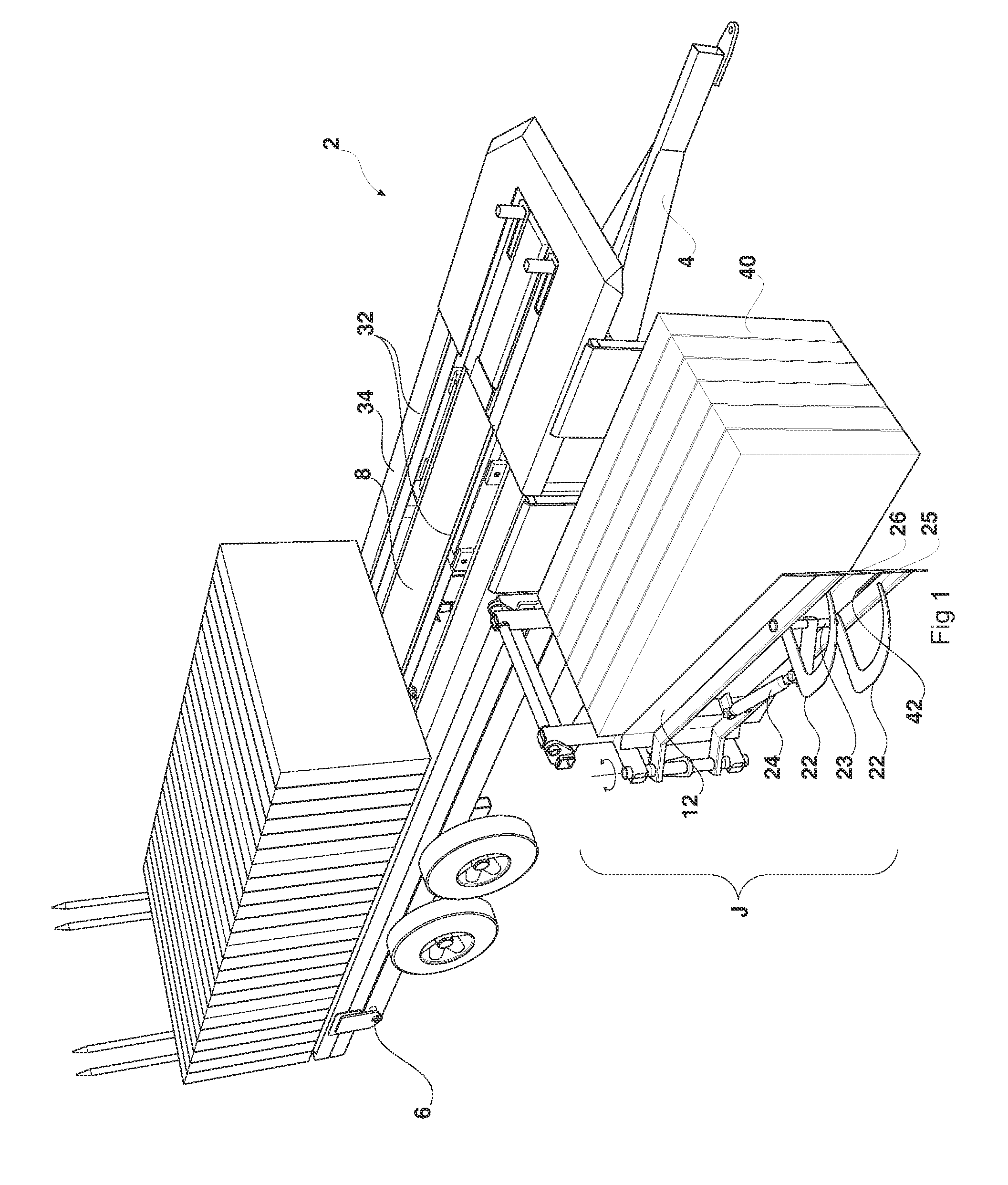
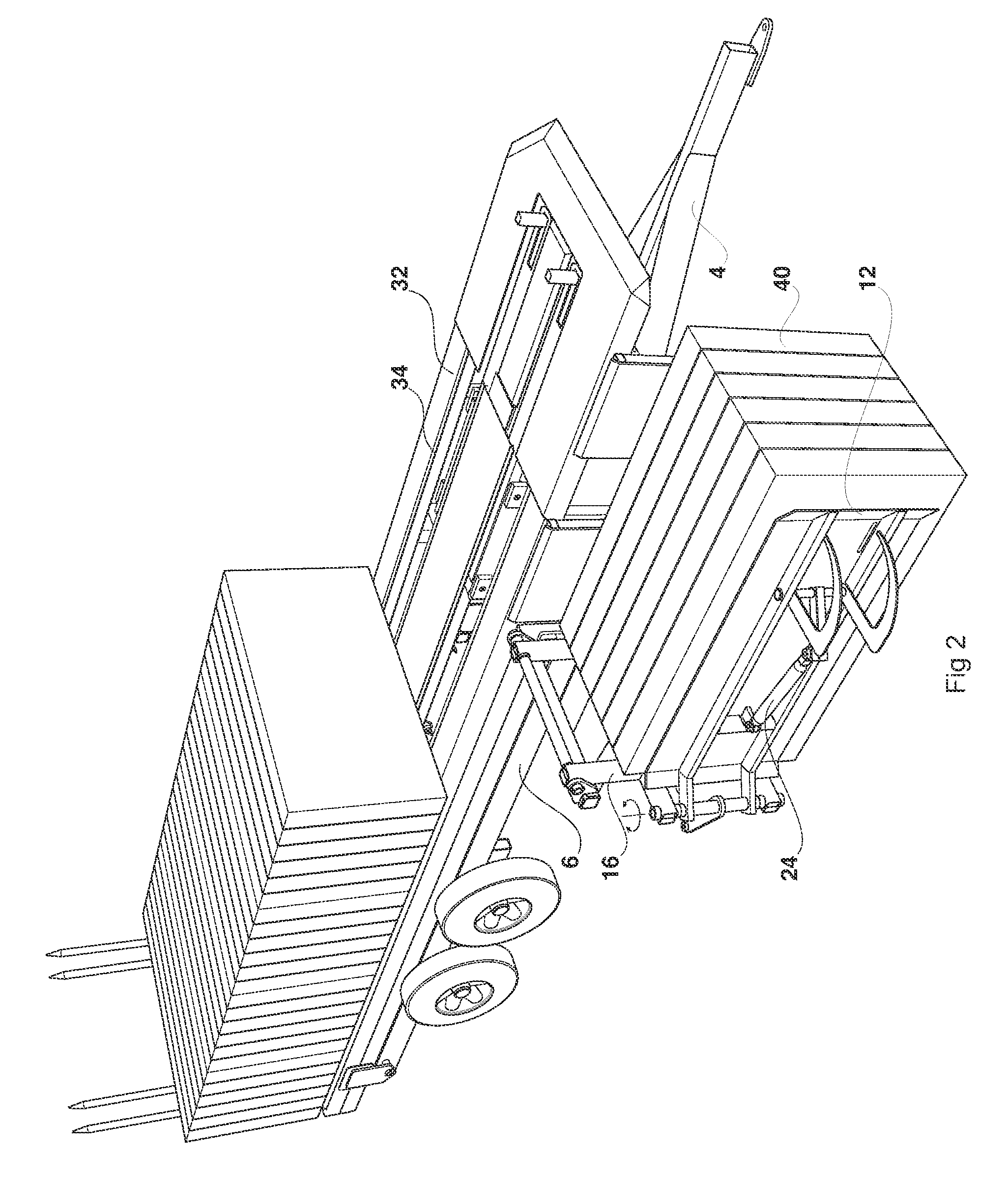
[0032]The hay bale stacker (2) includes a trailer (4) consisting of a chassis component (6) and a hay bale platform (8). The hay bale platform (8) is raised hydraulically and pivots around axis (10) with a pair of hydraulic cylinders that are interconnected to a Multi-stage cylinder mounted on the trailer (4).

[0033]The hay bale clamping assembly (J) includes a first planer clamping member (12) and a second planer clamping member (14) positioned substantially perpendicular to one another. The first clamping member (12) is pivotally connected to a rear frame section (16) via a hinge joint (18) and controlled by movement of the hydraulic cylinder (20).

[0034]The first clamping member (12) also includes a curved spike section (22) that pivots about hinge (23) by action of the hydraulic cylinder (24). The curved spike section (12) having ends (25) and (26) that are adapted to be inserted into a bale of hay so as to removably secure the hay between the clamping members.

[0035]Additionally, ...


PUM

PropertyMeasurementUnit
Angleaaaaaaaaaa

Abstract

An apparatus and method for stacking hay bales. The hay bale stacker includes a trailer having chassis and a platform, a hay clamping assembly (J) positioned at a longitudinal edge of the platform, the clamping assembly is pivotally coupled to the hay bale platform to selectively move between a horizontal bale clamping position and a vertical bale unloading position.

Description

FIELD OF THE INVENTION[0001]The present invention, relates to a system and method for loading, stacking and / or handling bales of hay.[0002]In particular, the present invention relates to a loading and stacking apparatus that includes a bale loading and moving mechanism to retrieve a bale of hay and stack it on to a bale-accumulating platform.[0003]Hay, when harvested, is traditionally collected into a variety of shapes and sizes depending on the device employed in forming the bale. A typical bale has a regular geometry, such as a rectangle. The weight of such bales varies depending upon its size and composition; however, with modern farming techniques bales are of a considerable weight that makes their handling and transportation problematic at times.[0004]When a bale of hay is formed they are typically deposited onto the ground and vehicles, such as wagons or trucks, are driven over the fields to where the bales are located and then lifted onto the vehicles by some lifting apparatu...

Claims


Application Information

Patent Timeline
IPC IPC(8): B60P1/00B65G57/00B65G47/04
CPCA01D90/08A01D85/005
Inventor SMITH, ADRIAN
Owner ASHMORE ENG PTY LTD
Why Eureka
Try Eureka