Scroll compressor capacity modulation with hybrid solenoid and fluid control

Inactive Publication Date: 2011-06-09
DANFOSS SCROLL TECH
View PDF7 Cites 45 Cited by
  • Summary
  • Abstract
  • Description
  • Claims
  • Application Information

AI Technical Summary

Benefits of technology

[0008]A scroll compressor includes a compressor shell having first and second scroll members. The scroll members each have a base and a generally spiral wrap extending from its base. The generally spiral wraps of the first and second scroll members interfit to define compression chambers. A shaft causes the second scroll member to orbit relative to the first scroll member. At least one bypass port is formed in a base of one scroll member, and c

Problems solved by technology

However, providing power to these valves has been somewhat challenging.
In addition, since the valve is within the shell, it is somewhat difficult to cool the v

Method used


Image

  • Scroll compressor capacity modulation with hybrid solenoid and fluid control
  • Scroll compressor capacity modulation with hybrid solenoid and fluid control
  • Scroll compressor capacity modulation with hybrid solenoid and fluid control

Examples


first embodiment

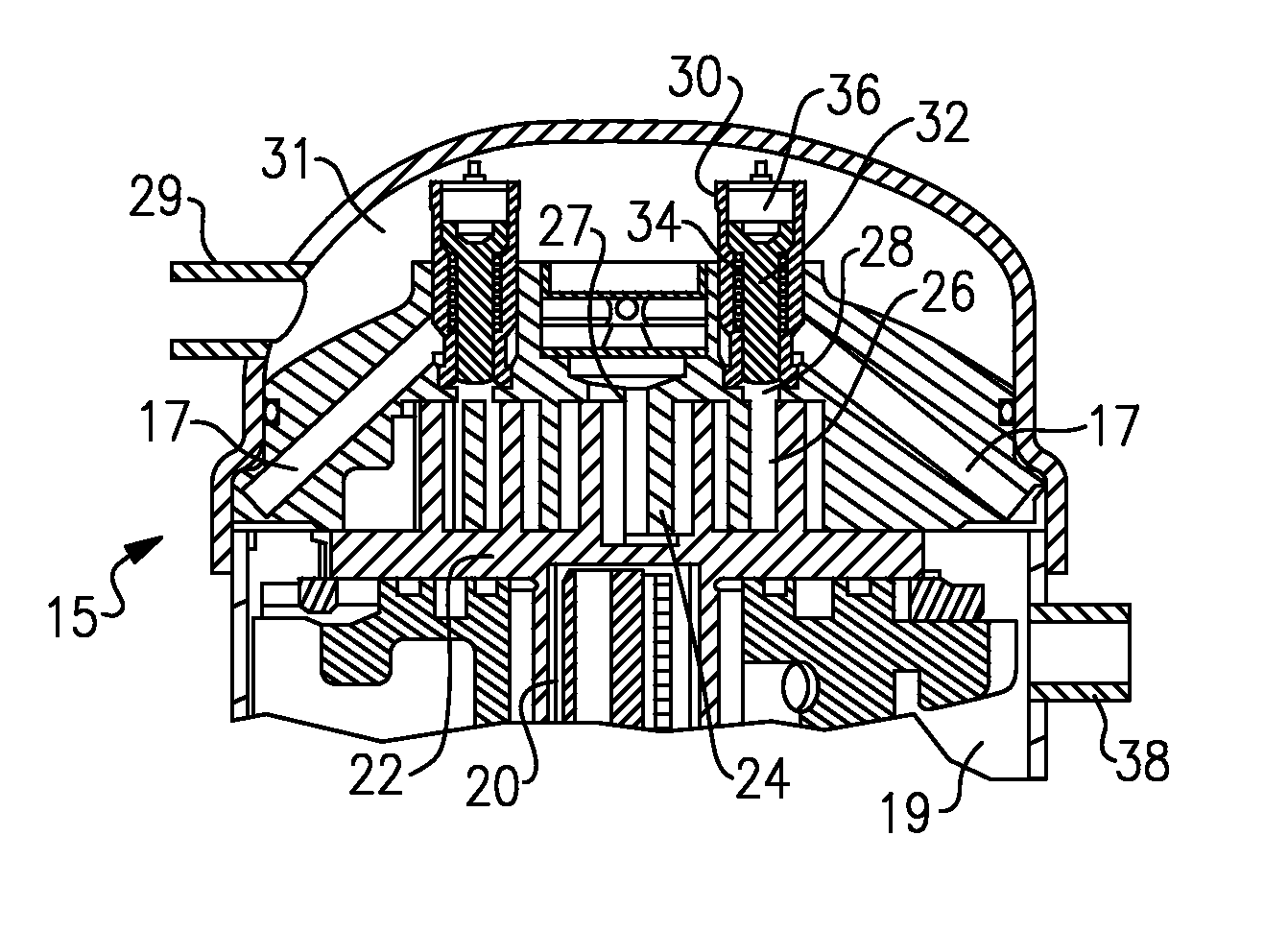
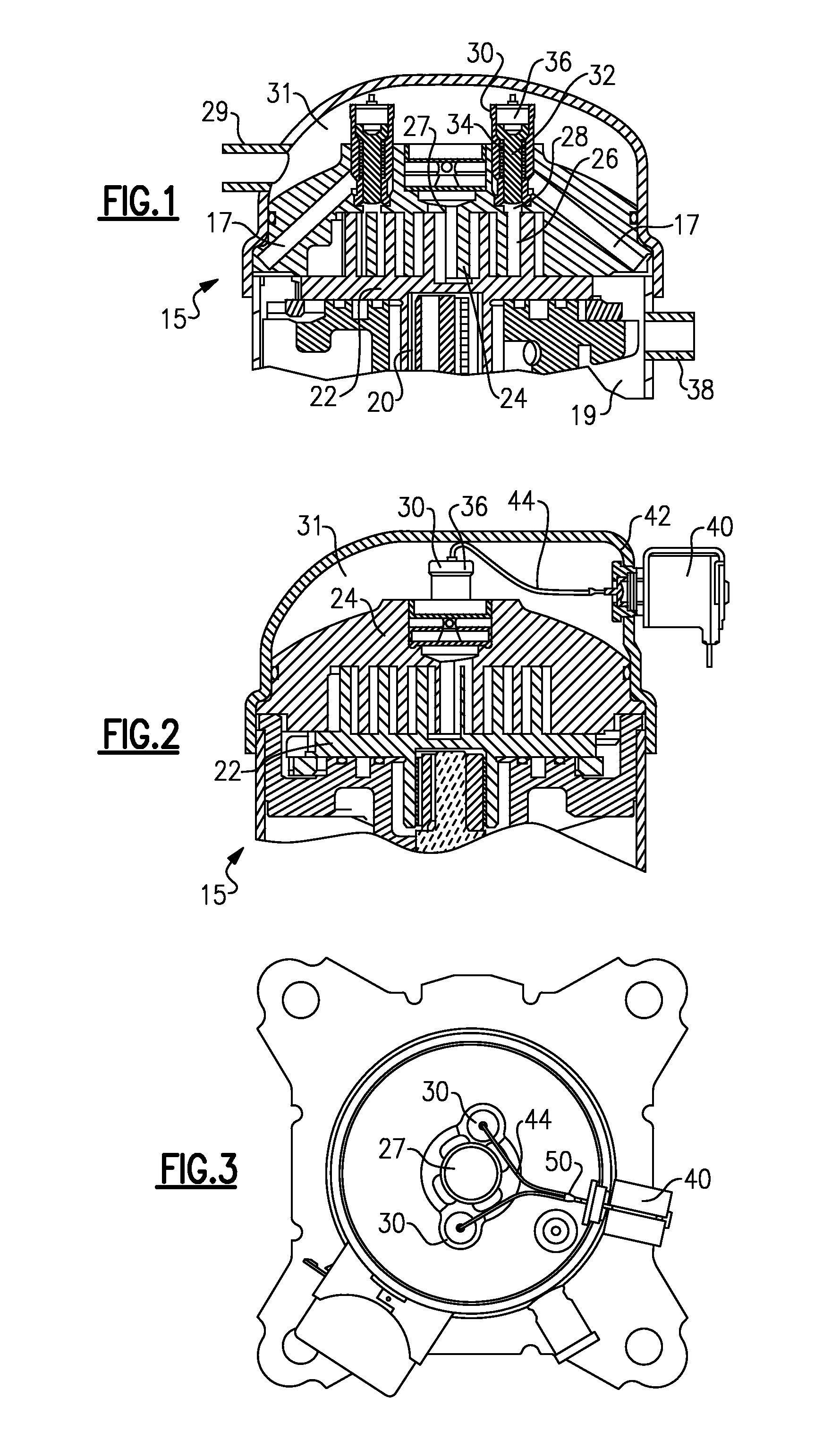
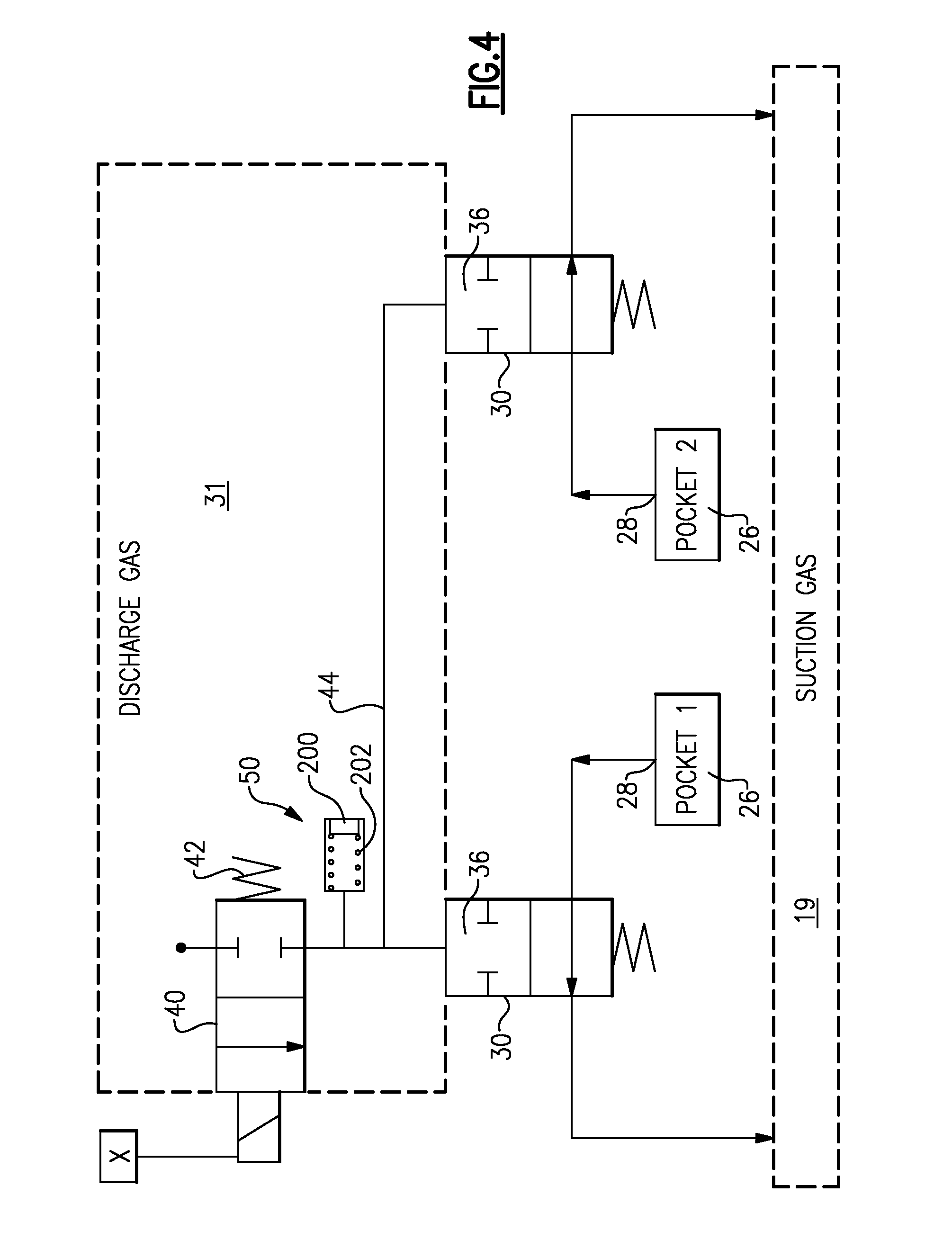
[0021]As shown in FIG. 4, in a first embodiment, a single solenoid is driven to a position by a spring 42 where it blocks the flow of pressurized refrigerant from the discharge pressure plenum 31 to the control chamber 36 on each of the valve assemblies 30. However, when the solenoid 40 is energized, it will allow the flow of the pressurized fluid to the pressure chambers 36, and this will block the bypass of refrigerant from the compression chambers through the ports 28, and back to the suction plenum 19.

[0022]As shown, the valve 50 may be as simple as a valve body including a ball 200 spring biased by spring 202 to a closed position. If the valve 40 fails, and once the pressure in the plenum 31 reaches a significantly high level, then the valve 200 will open, and pressurized gas can flow to close the valves 30. Of course, other valve arrangements could be utilized.

[0023]The embodiment of FIG. 4 can achieve two steps of capacity. The compressor can supply 100% capacity, or some red...

second embodiment

[0024]FIG. 5 shows a second embodiment wherein there are a pair of solenoids 140, each connected to separate valve housings 130 through fluid supply lines 134. A worker of ordinary skill in the art can review the FIG. 1-3 embodiments, and understand how to mount the solenoids 140, and communicate to the valve housings 130. In this manner, the control X can now achieve three steps of capacity control. Either full capacity can be achieved by closing both valves 130, a first reduced step can be achieved by opening one of the valves, a second step can be achieved by opening both valves. In fact, if the amount of bypass provided by the two separate ports 128 differs, then even a third step of reduced capacity can be achieved. That is, should the left-hand side port 128 reduce capacity by more than the right-hand side port 128, then one could achieve the capacity step of having the left-hand port open, the right-hand port open, or both ports open.

[0025]Also, in other embodiments, a single...


PUM


Abstract

A scroll compressor includes a compressor shell having first and second scroll members. The scroll members each have a base and a generally spiral wrap extending from its base. The generally spiral wraps of the first and second scroll members interfit to define compression chambers. A shaft causes the second scroll member to orbit relative to the first scroll member. At least one bypass port is formed in a base of one scroll member, and communicates with at least one of the compression chambers. The bypass port communicates with a passage leading to a suction pressure chamber within the compressor shell. A solenoid valve is movable between a reduced capacity position and a full capacity position, and selectively supplies a pressurized fluid to a fluid valve associated with the bypass port, such that movement of the solenoid can control whether the bypass port is open or closed.

Description

BACKGROUND OF THE INVENTION[0001]A scroll compressor is provided with a capacity modulation control, including a solenoid valve which can be moved to selectively control the supply of fluid to bypass valves to move the compressor between a full capacity and a reduced capacity position.[0002]Scroll compressors are becoming widely utilized in refrigerant compression applications. In a scroll compressor, a pair of generally spiral wraps interfit to define compression chambers. One of the wraps is caused to orbit relative to the other, and as the two move, the size of the compression chamber is reduced, thereby compressing an entrapped refrigerant.[0003]Under certain conditions, the capacity, or amount of refrigerant compressed by the compressor, may be desirably reduced. As an example, if the compressor is incorporated into an air conditioning system, and the cooling load is low, then it is more energy efficient to compress less refrigerant.[0004]Various ways are known for reducing the...

Claims


Application Information

Patent Timeline
IPC IPC(8): F04C28/26F04C18/02
CPCF04C18/0215F04C28/26F04C23/008
Inventor FIELDS, GENEHILL, JOE T.MILLIFF, TRACY L.PATEL, TAPESH P.UPADHYE, HARSHAL R.PARASTAR, BEHZADCHRISTENSEN, OLE HOLST
Owner DANFOSS SCROLL TECH
Why Eureka
Try Eureka