Electrolyte membrane/electrode structure and fuel cell

a technology of electrolyte membrane and electrolyte membrane, which is applied in the direction of solid electrolyte fuel cells, fuel cells, electrical apparatus, etc., can solve the problems of insufficient strength, disadvantageous lowering of sealing performance, damage to electrolyte membrane b>1/b>, etc., to achieve desired durability, prevent damage to solid polymer electrolyte membrane, and improve outer circumferential strength

Inactive Publication Date: 2011-06-09
HONDA MOTOR CO LTD
View PDF8 Cites 29 Cited by
  • Summary
  • Abstract
  • Description
  • Claims
  • Application Information

AI Technical Summary

Benefits of technology

[0013]In the present invention, the first electrode and the second electrode having different surface areas are provided on both surfaces of the solid polymer electrolyte membrane to form the membrane electrode assembly, and in the membrane electrode assembly of this type, so-called “stepped-type MEA”, the reinforcement sheet member is provided on the frame shaped surface exposed from the outer circumferential end of the first electrode of the solid polymer electrolyte membrane. Improvement in the strength of the outer circumferential portion of the stepped-type MEA is achieved, and it becomes possible to prevent damage of the solid polymer electrolyte membrane as much as possible.
[0014]Further, since the membrane electrode assembly is a stepped-type MEA, no shearing force is generated in the outer circumferential portion of the stepped-type MEA due to seal displacement. Accordingly, the desired sealing performance and the desired durability can be achieved advantageously.

Problems solved by technology

However, in Japanese Laid-Open Patent Publication No. 05-021077, since the protective membrane 6 is made of a thin film sheet having a thickness of 50 μm or less, when the solid polymer electrolyte membrane 1 is sandwiched between the gas seal members 7, the sufficient strength cannot be obtained.
Thus, the outer marginal portion of the solid polymer electrolyte membrane 1 to which the protective membranes 6 are attached may be deformed, the solid polymer electrolyte membrane 1 may be damaged, and the sealing performance may be lowered disadvantageously.

Method used


Image

  • Electrolyte membrane/electrode structure and fuel cell
  • Electrolyte membrane/electrode structure and fuel cell
  • Electrolyte membrane/electrode structure and fuel cell

Examples


Embodiment Construction

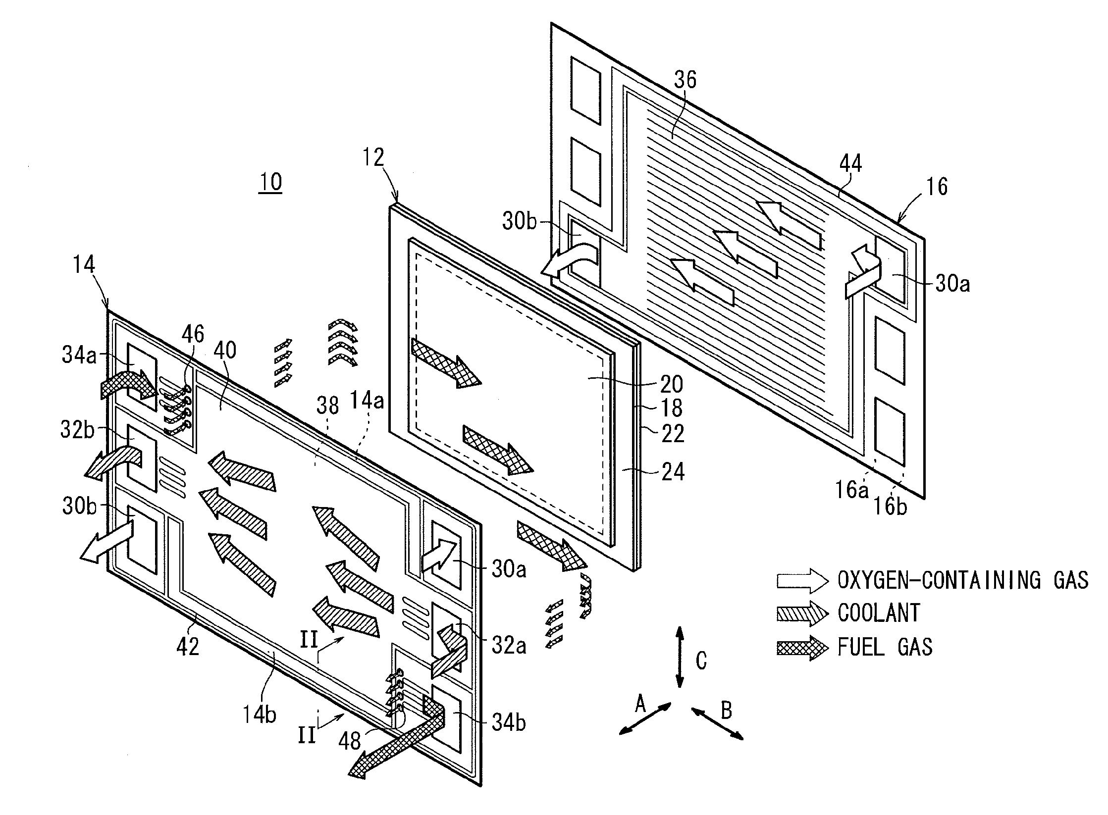
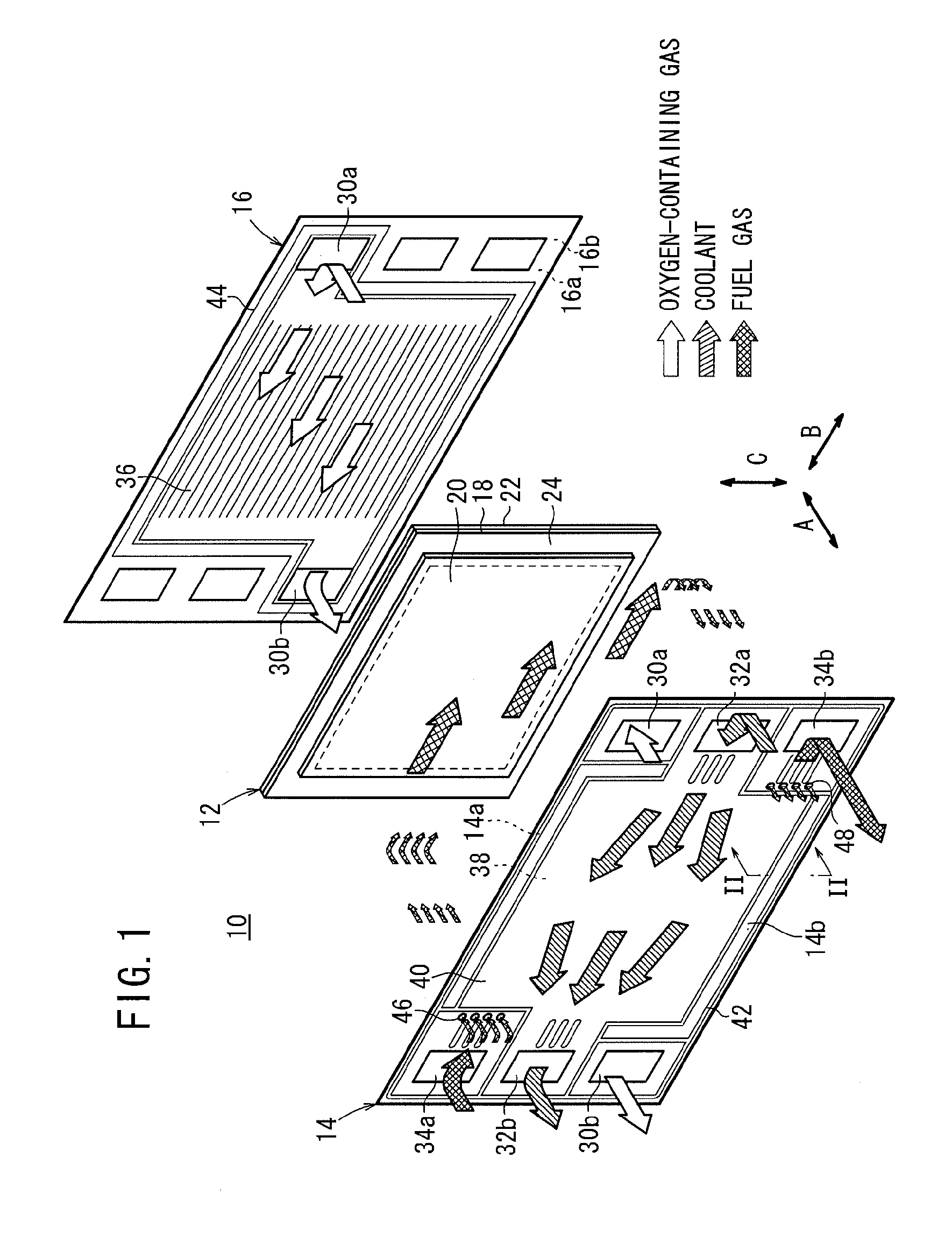
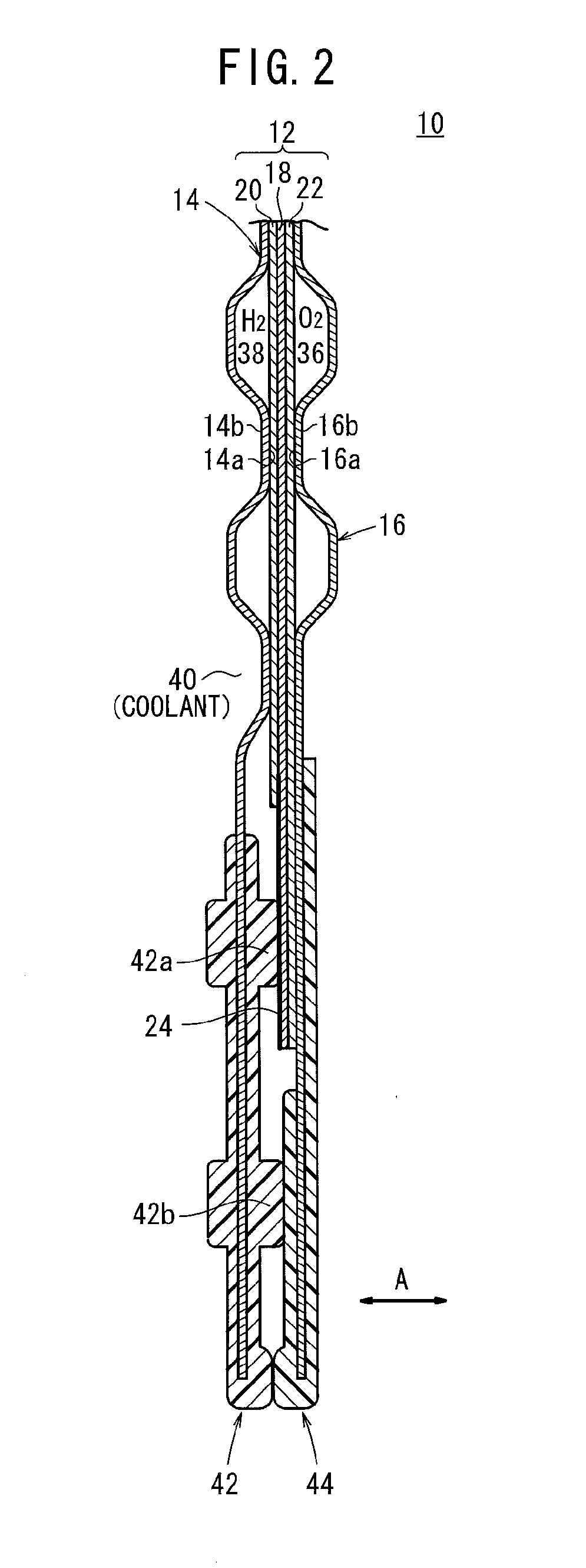
[0019]As shown in FIGS. 1 and 2, a fuel cell 10 according to an embodiment of the present invention includes a membrane electrode assembly 12 according to the present embodiment and first and second separators 14, 16 sandwiching the membrane electrode assembly 12. For example, the first and second separators 14, 16 are steel plates, stainless steel plates, aluminum plates, plated steel sheets, or metal plates having anti-corrosive surfaces formed by surface treatment. Alternatively, the first and second separators 14, 16 are made of carbon material or the like.

[0020]The membrane electrode assembly 12 includes a solid polymer electrolyte membrane 18, an anode (first electrode) 20 and a cathode (second electrode) 22 sandwiching the solid polymer electrolyte membrane 18. The surface area of the anode 20 is smaller than the surface area of the cathode 22. A reinforcement sheet member 24 is provided on a frame-shaped surface of the solid polymer electrolyte membrane 18 exposed to the out...


PUM

PropertyMeasurementUnit
thicknessaaaaaaaaaa
surface areaaaaaaaaaaa
circumferenceaaaaaaaaaa

Abstract

An electrolyte membrane/electrode structure constituting a fuel cell comprises a solid polymer electrolyte membrane, an anode side electrode and a cathode side electrode sandwiching the solid polymer electrolyte membrane. The anode side electrode is provided with an electrode catalyst layer and a gas diffusion layer abutting on one side of the solid polymer electrolyte membrane and exposing the outer circumference thereof in the shape of a frame, and the cathode side electrode is provided with an electrode catalyst layer and a gas diffusion layer abutting on the other side of the solid polymer electrolyte membrane. A reinforcing sheet member is arranged on the frame-shaped surface of the solid polymer electrolyte membrane projecting from the outer circumference of the gas diffusion layer.

Description

TECHNICAL FIELD[0001]The present invention relates to a membrane electrode assembly (electrolyte membrane / electrode structure) including a first electrode and a second electrode, and a solid polymer electrolyte membrane interposed between the first electrode and the second electrode. Also, the present invention relates to a fuel cell including the membrane electrode assembly and first and second separators sandwiching the membrane electrode assembly.BACKGROUND ART[0002]Generally, a solid polymer electrolyte fuel cell employs a solid polymer electrolyte membrane. The solid polymer electrolyte membrane is a polymer ion exchange membrane. The solid polymer electrolyte membrane is interposed between an anode and a cathode each including a catalyst layer (electrode catalyst) and a gas diffusion layer (porous carbon) to form a membrane electrode assembly (MEA). The membrane electrode assembly is interposed between separators (bipolar plates) to form the fuel cell. Normally, in use, predet...

Claims


Application Information

Patent Timeline
Patent Type & Authority Applications(United States)
IPC IPC(8): H01M8/10
CPCH01M8/0273Y02E60/521H01M8/1004H01M8/0276Y02E60/50H01M8/0258H01M8/2483
Inventor ISHIDA, KENTAROISOBE, TAKEAKINANAUMI, MASAAKIMATSUBARA, TAKESHI
Owner HONDA MOTOR CO LTD
Why Eureka
Try Eureka