Remote controlled power supply system

a power supply system and remote control technology, applied in the direction of instruments, data switching details, liquid/fluent solid measurement, etc., can solve the problems of /sup>c operation being disabled, data loss and system interruption, machine down, etc., to facilitate problem elimination more quickly and reduce the time of problem determination

Inactive Publication Date: 2011-06-09
ZIPPY TECH
View PDF7 Cites 5 Cited by
  • Summary
  • Abstract
  • Description
  • Claims
  • Application Information

AI Technical Summary

Benefits of technology

[0008]In view of the convention control technique that causes operation interruption of a system used to transmit control information once the power supply malfunctions and results in loss of the control information of the entire power supply system and makes controlling the power supply not possible, the primary object of the present invention is to provide an improved control circuit architecture to enable the administrators to distinguish malfunction of a power supply or a control system to reduce problem determination time and facilitate problem elimination more quickly.

Problems solved by technology

But malfunction of the power supplies 91 still takes place occasionally and results in machine down, data loss and system interruption.
It mainly caused by flaws of control circuit architecture of the power supplies 91.
However, in the event that some data processing system 92 does not support I2C operation is disabled (some computer motherboards do not provide support needed).
Moreover, the address setting of I2C of the data processing system 92 could be different from the power supplies 91 and result in errors and incorrect data access.
The different information at two ends could cause access errors of the data processing system 92, and the administrators at the remote end cannot acquire the actual conditions of the power supplies 91.
Another drawback that is difficult to eliminate is machine down of the data processing system 92 that results in failure of I2C data access through the data processing system 92.
And the remote control equipment 93 cannot get the correct information.
Whether the power supplies 91 function correctly or incorrectly, the administrators cannot get the accurate status remotely.
As a result, troubleshooting is difficult.
All the aforesaid problems still exist in the conventional circuit architecture.

Method used


Image

  • Remote controlled power supply system
  • Remote controlled power supply system
  • Remote controlled power supply system

Examples


Embodiment Construction

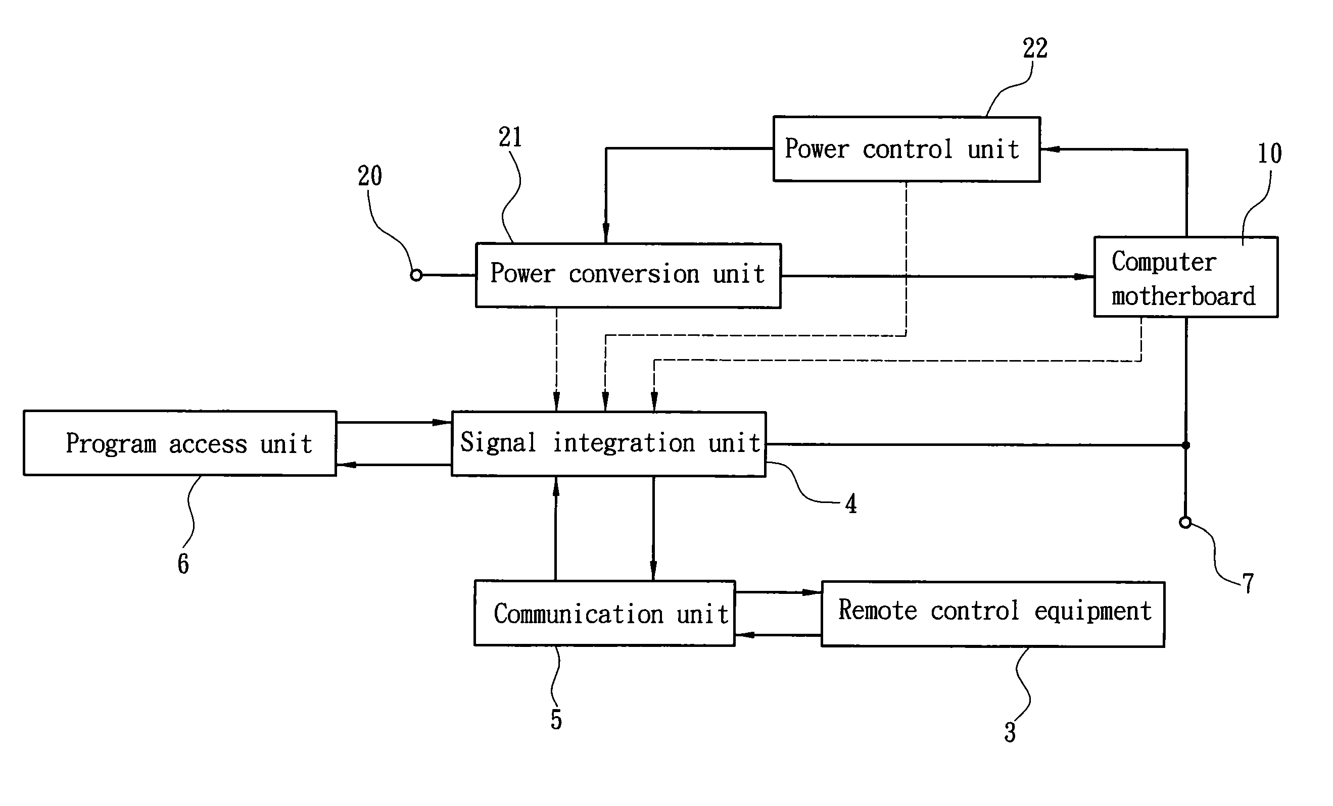
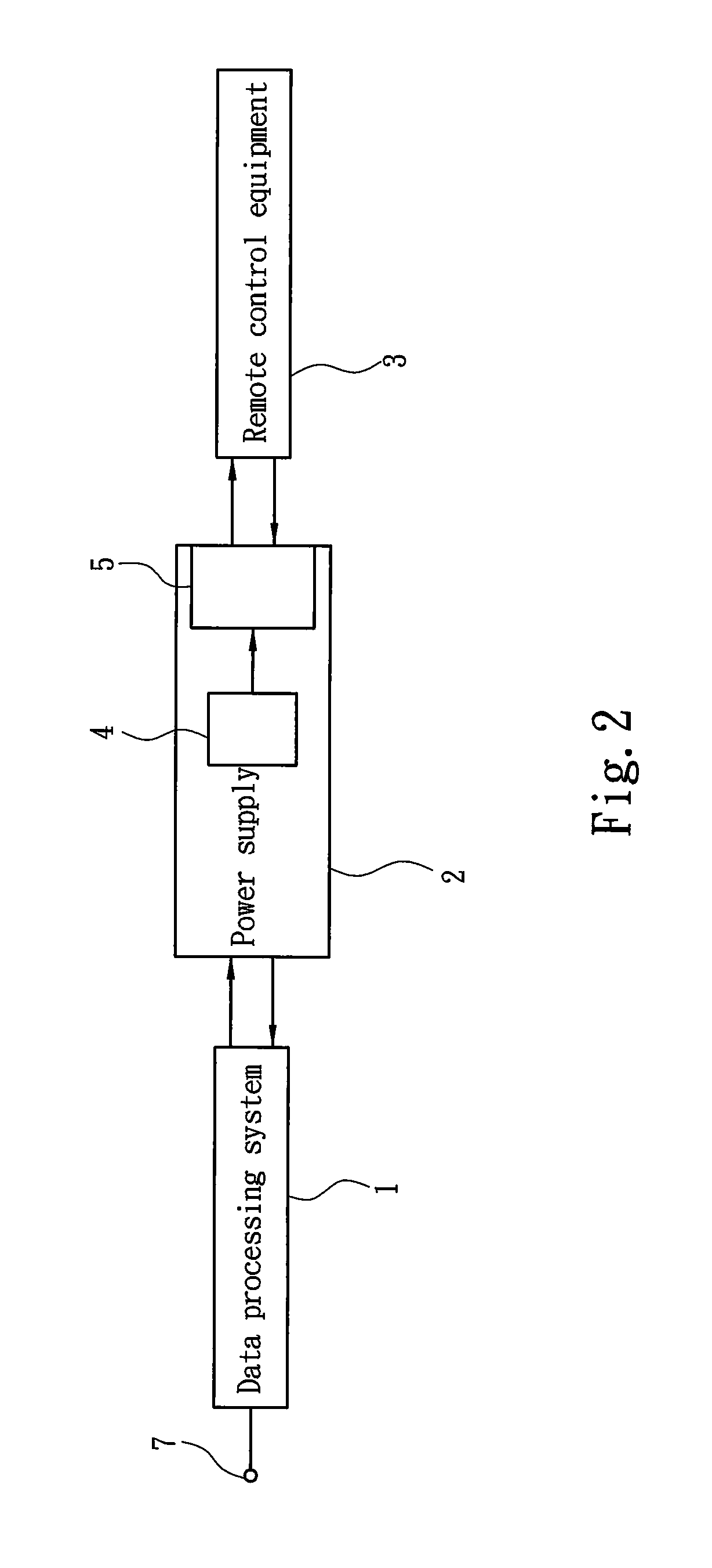
[0015]The present invention aims to provide a remote controlled power supply system. Refer to FIG. 2 for the fundamental circuit architecture of the present invention. The power supply system according to the present invention includes a data processing system 1 and at least one power supply 2. The power supply 2 may be a single set or consist of multiple sets with multiple outputs. Thus, the data processing system 1 can connect to one or more sets of power supply 2 correspondingly. FIG. 2 shows the data processing system 1 is connected to only one set of power supply 2. The data processing system 1 outputs a power source ON / OFF signal to drive the power supply 2 to switch to a working state or a sleeping state (the working state and sleeping state aim to meet ATX power supply specifications that is a technique known in the art, thus details are omitted herein). The data processing system 1 may be a computer motherboard 10 activated through an ON / OFF switch 7. An embodiment is depic...


PUM


Abstract

A remote controlled power supply system includes a data processing system and at least one power supply. The data processing system outputs a power source ON/OFF signal to drive the power supply to switch either in a working state or a sleeping state. The power supply includes a signal integration unit and a communication unit. The signal integration unit receives a working parameter of the power supply and outputs a first ON/OFF signal to drive the data processing system to output the power ON/OFF signal to switch the state of the power supply state. The communication unit is linked to the signal integration unit to receive the working parameter and output the working parameter to a communication network. The administrators can acquire the working parameter through a remote control equipment and control the power supply at the remote site.

Description

FIELD OF THE INVENTION[0001]The present invention relates to a remote controlled power supply system and particularly to a system allowing remote observation of power supply status and control ON / OFF of the power supply in a remote manner.BACKGROUND OF THE INVENTION[0002]A conventional control system for multiple power supplies (used on servers, uninterrupted power system and the like), referring to FIG. 1, generally includes multiple sets of power supplies 91 in a cabinet or multiple cabinets, or operating independently at different locations. The power supplies 91, aside from connecting to individual loads, also are connected to a data processing system 92 which can be installed on a bus panel in the same cabinet or a computer connected to the power supplies 91 through wires. The data processing system 92 receives the power from the power supplies 91 to perform operation. Output and abnormal conditions of the power supplies 91 are read by the data process system 92 and sent to a r...

Claims


Application Information

Patent Timeline
Patent Type & Authority Applications(United States)
IPC IPC(8): G06F1/26
CPCH04L12/10G06F1/266
Inventor SHIH, TSUN-TECHAN, YU-YUANCHANG, HENG-CHIAYANG, CHIEHSHIH, KUANG-LUNG
Owner ZIPPY TECH
Why Eureka
Try Eureka