Shaped heat sinks to optimize flow

a heat sink and flow optimization technology, applied in cooling/ventilation/heating modification, semiconductor devices, lighting and heating apparatus, etc., can solve the problems of limiting the flow of cooling water, limiting the efficiency of simple fan-based cooling systems, and increasing the difficulty of thermal management of these devices, so as to improve the overall efficiency of such systems and improve the efficiency of heat removal

Inactive Publication Date: 2011-06-16
GENERAL ELECTRIC CO
View PDF40 Cites 22 Cited by
  • Summary
  • Abstract
  • Description
  • Claims
  • Application Information

AI Technical Summary

Benefits of technology

[0004]For electronic equipment cooling, the use of synthetic jets in conjunction with cooling fans can sometimes be used to improve the efficiency of heat removal. However, there is a need in the art for further improvements in such cooling systems to improve the overall efficiency of such systems.

Problems solved by technology

As the size of semiconductor devices has continued to shrink and circuit densities have increased accordingly, thermal management of these devices has become more challenging.
However, simple fan-based cooling systems can be limited by several factors, including the physical constraints of the system to be cooled, the power available to run the fan, and noise associated with fan operation.
While some applications may be able to generate cooling flow with a smaller fan, or with systems other than fans, such systems limit the amount of cooling flow, and therefore the total heat transfer available from such systems.

Method used


Image

  • Shaped heat sinks to optimize flow
  • Shaped heat sinks to optimize flow
  • Shaped heat sinks to optimize flow

Examples


Embodiment Construction

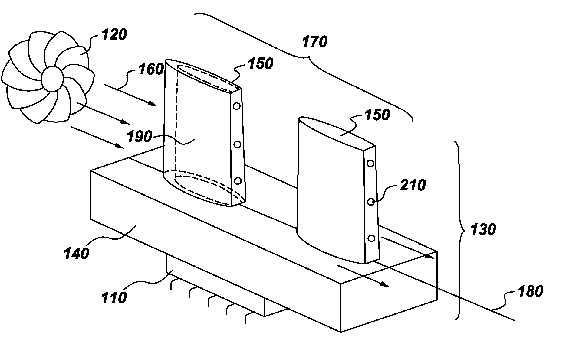
[0019]As noted above, many cooling applications depend on forced convection to remove thermal losses from temperature limited electronic devices. For a common electronics cooling solution requiring dissipation of 20 Watts or more of heat flow, a heat sink and fan are commonly used, especially for volume-constrained applications. The heat sink can be thermally attached to an individual device, to a number of devices via a board or perhaps module casing, or to a still larger system level casing. There are various heat sink types, for example, extruded fin, bonded fin, and folded fin. Factors to consider when deciding which type to specify for an application include the volume, surface area, material compatibility, fin efficiency, weight, cost, and attachment method, among others. The fan provides mechanical work to drive air through the heat sink. It requires power to do so, almost always in the form of electrical power. The fan volumetric flow rate, pressure rise, and fan efficiency ...


PUM


Abstract

A heat sink with shape-optimized fins provides for improved heat transfer. Synthetic jets create vortices which enhance heat transfer and cooling of downstream fins, while the shape of the fins limits pressure drop in the flow over the cooling fins.

Description

CROSS REFERENCE TO RELATED APPLICATIONS[0001]This application claims the priority and benefit of U.S. Provisional Application No. 61 / 285,564, entitled “ENERGY STORAGE DEVICE AND METHOD” filed on 11 Dec. 2009, which is incorporated in its entirety herein by reference.TECHNICAL FIELD[0002]The systems and techniques described relate generally to thermal management systems, and more particularly, to systems and methods for packaging synthetic jets.DISCUSSION OF RELATED ART[0003]As the size of semiconductor devices has continued to shrink and circuit densities have increased accordingly, thermal management of these devices has become more challenging. In the past, thermal management in semiconductor devices was often addressed through the use of forced convective air cooling, either alone or in conjunction with various heat sink devices, and was accomplished through the use of fans. However, simple fan-based cooling systems can be limited by several factors, including the physical constr...

Claims


Application Information

Patent Timeline
Patent Type & Authority Applications(United States)
IPC IPC(8): F28F7/00
CPCF28D2021/0029F28F3/02H01L23/467F28F2250/02H01L2924/0002H05K7/20H01L2924/00
Inventor SALAPAKKAM, PRADEEP CHANDRA BABULI, RIARIK, MEHMETGERSTLER, WILLIAM DWIGHTWHALEN, BRYAN PATRICK
Owner GENERAL ELECTRIC CO
Why Eureka
Try Eureka