Supercharge Your Innovation With Domain-Expert AI Agents!

Rotating electrical machine

a technology of rotating electrical machines and rotating shafts, which is applied in the direction of magnetic circuits, magnetic bodies, and magnetic circuits characterised by magnetic materials, etc., can solve the problems of increasing loss, increasing heat generation in the core, and increasing loss, so as to improve temperature distribution and reliability. high

Active Publication Date: 2011-06-16
MITSUBISHI HEAVY IND LTD
View PDF16 Cites 13 Cited by
  • Summary
  • Abstract
  • Description
  • Claims
  • Application Information

AI Technical Summary

Benefits of technology

The invention is about a rotating electrical machine that improves temperature distribution, especially near the stator winding, to increase reliability. The machine has a rotor and stator with a gap between them. The stator core is made up of multiple split pieces, each containing teeth for inserting the stator winding. The stator core also has different magnetic permeability at the axial end and the axial central portion. This results in better temperature distribution and higher reliability of the rotating electrical machine.

Problems solved by technology

That is, by increasing ducts in number for the purpose of cooling a winding, there is a possibility that loss, that is, heat generation is increased in the core.
Since a direction of magnetic flux in teeth and a direction of magnetic flux in a core back are perpendicular to each other, however, a magnetic flux is hard to pass through the core back, so that there is a possibility of an increase in loss.
In the case where a magnetic flux density close to saturation magnetization is acted, a magnetic resistance increases since a magnetic material is equivalent in magnetic permeability to an air, so that there is also a possibility that a magnetic flux makes a circuit in an axial direction in the same manner at the end as described above and a magnetic flux in a direction of lamination increases to lead to an increase in loss.

Method used


Image

  • Rotating electrical machine
  • Rotating electrical machine
  • Rotating electrical machine

Examples


first embodiment

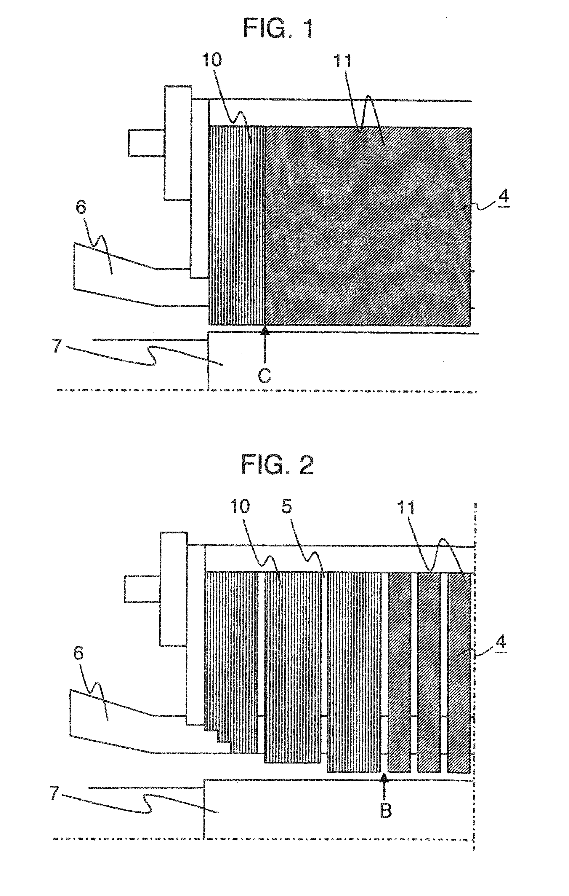
[0037]FIG. 1 is a cross sectional view of a rotating electrical machine according to the invention in which a stator core 4 is viewed in a circumferential direction. FIG. 1 shows a half of the rotating electrical machine in a diametrical direction and a portion thereof close to an axial end.

[0038]Grain oriented magnetic steel sheets 10 are laminated at an axial end of the stator core 4, non-oriented magnetic steel sheets 11 are laminated at an axial central portion of the stator core, and the respective steel sheets are formed by split pieces punched from a steel strip in a direction, in which teeth 1 are perpendicular to a direction of rolling as shown in FIG. 11A. Accordingly, a circumferential direction of the stator core substantially corresponds to the direction of rolling and a diametrical direction thereof substantially corresponds to a vertical direction to the direction of rolling.

[0039]Thereby, in the first embodiment, magnetic steel sheets which are different in magnetic ...

second embodiment

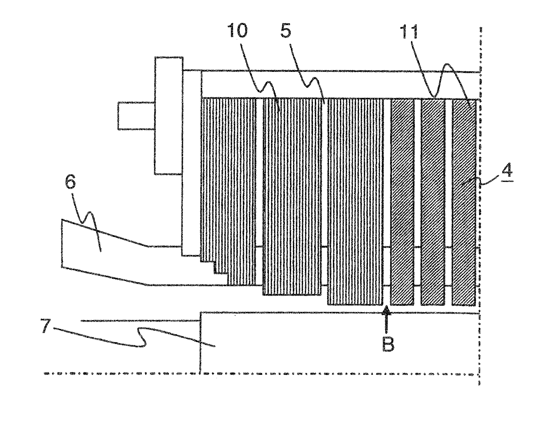
[0048]FIG. 2 shows a structure of the stator core 4 in the invention. As shown in FIG. 2, an axial spacing between cooling ducts 5 in an axial central region of the stator core 4 is made smaller as compared with an average axial spacing of the cooling ducts, which is obtained by dividing an axial length of the stator core by the total number of cooling ducts, so that flow rate of the cooling medium through the axial central region of the stator core 4 is increased. In the case where a conventional structure is applied, a magnetic material is decreased in volume in an area, in which the number of cooling ducts is increased, so that an increase in magnetic flux density of the core and an increase in loss are caused.

[0049]In contrast, in the second embodiment, magnetic steel sheets used generally in rotating electrical machines are employed as steel sheets used for the stator core 4. The stator core 4 is formed from split pieces each punched from a steel strip as shown in FIG. 11A such...

third embodiment

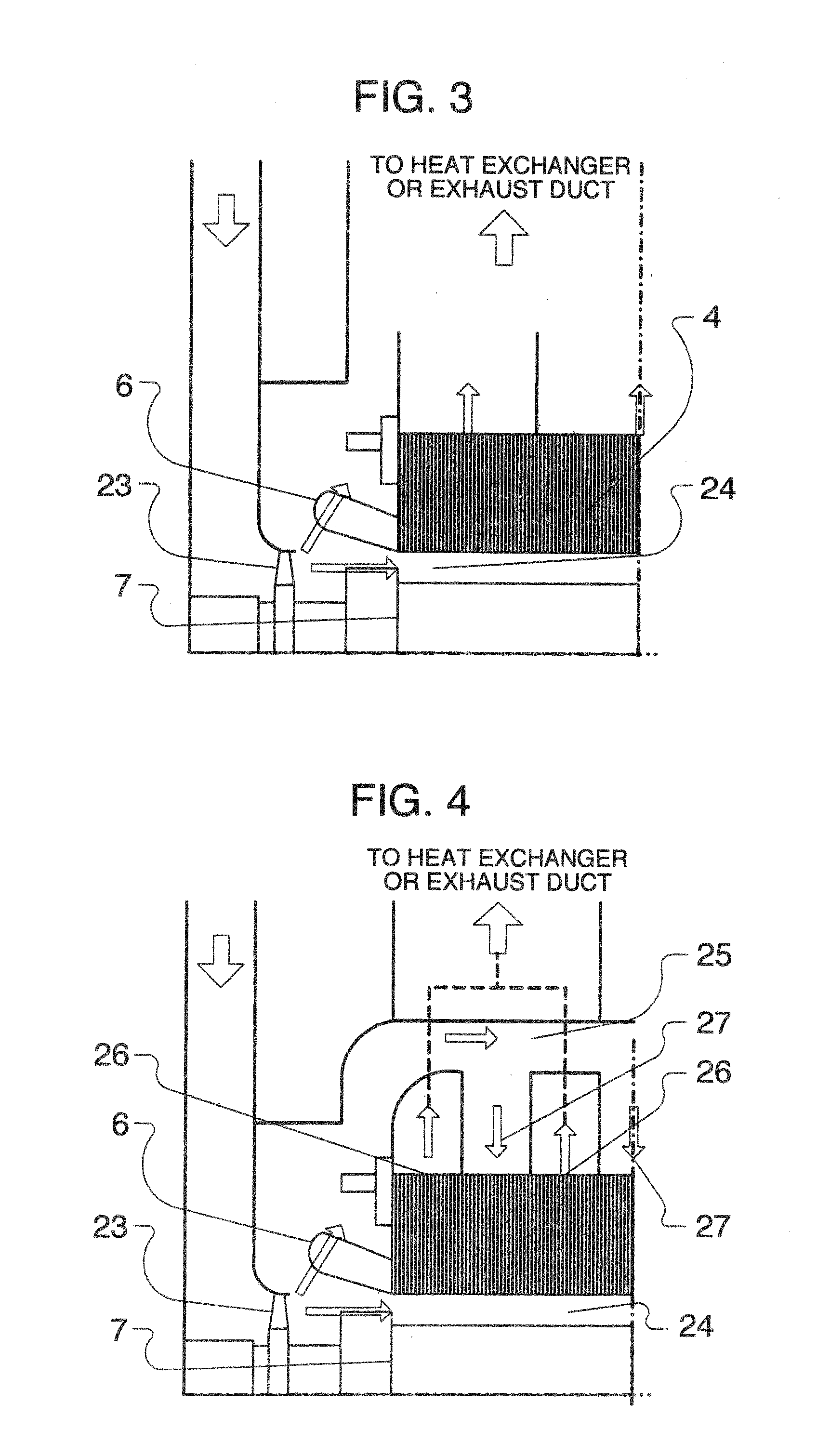
[0058]FIG. 5 shows a structure of the stator core in the invention. In FIG. 5, non-oriented magnetic steel sheets 11 are laminated to form the exhaust section 26b positioned in an axial central region, and grain oriented magnetic steel sheets 10 are laminated to form the exhaust section 26a other than the exhaust section 26b, and the intake sections 27a, 27b. Here, the non-oriented magnetic steel sheets 11 are made of split pieces punched from a steel strip as shown in FIG. 11A.

[0059]The exhaust section 26b and positioned downstream of the cooling medium flowing path is expected to be increased in temperature since the cooling medium flows thereinto after mainly passing through the intake sections 27a, 27b. Hereupon, in the their embodiment, an axial spacing between the cooling ducts in the exhaust section 26b is made smaller than an average one in order to increase the quantity of a cooling medium flowing in the exhaust section 26b positioned in the axial central region.

[0060]Descr...


PUM


Abstract

A rotating electrical machine includes: a rotor comprising a rotor core and a field winding wound round the rotor core; and a stator comprising a stator core and a stator winding wound round the stator core. The stator is arranged in opposition to the rotor with a predetermined spacing therebetween. the stator core is formed by punching a split piece, which comprises teeth for insertion of the stator winding thereinto and a core back on an outer periphery thereof, from a magnetic steel sheet, and laminating a plurality of those circular configurations in an axial direction, in which a plurality of the split pieces are arranged in a circle in a circumferential direction. The stator core has magnetic steel sheets, which are different in magnetic permeability in a diametrical direction, laminated at an axial end region of and in an axial central region of the stator core.

Description

[0001]This application is a divisional application of U.S. application Ser. No. 12 / 428,875, filed Apr. 23, 2009, the entirety of which is incorporated herein by reference.BACKGROUND OF THE INVENTION[0002]The present invention relates to a rotating electrical machine, and more particularly, to a rotating electrical machine suitable for an arrangement, which is adopted in, for example, turbine-driven generators, etc. and of which a stator core is formed by laminating magnetic steel sheets.[0003]An explanation will be given to a conventional example of a stator core of a large-sized rotating electrical machine.[0004]As shown in FIGS. 11A and 11B, a stator core of a turbine-driven generator is formed into a cylindrical configuration by punching a steel sheet into sector-shaped split pieces from a steel strip and arranging the split pieces in plural in a circumferential direction to define a circular configuration to laminate the same in plural in an axial direction. FIG. 8 shows an exam...

Claims


Application Information

Patent Timeline
Patent Type & Authority Applications(United States)
IPC IPC(8): H02K1/16
CPCH02K1/02H02K1/20H02K1/16
Inventor NAKAHARA, AKIHITOMIKAMI, HIROYUKIIDE, KAZUMASATAKAHASHI, KAZUHIKOHATTORI, KENICHI
Owner MITSUBISHI HEAVY IND LTD
Features
  • R&D
  • Intellectual Property
  • Life Sciences
  • Materials
  • Tech Scout
  • Unparalleled Data Quality
  • Higher Quality Content
  • 60% Fewer Hallucinations
Learn More