Electric vehicle, taxing server, charging apparatus, drive management method, and program

Inactive Publication Date: 2011-06-16
SONY CORP
View PDF12 Cites 37 Cited by
  • Summary
  • Abstract
  • Description
  • Claims
  • Application Information

AI Technical Summary

Benefits of technology

[0018]A gasoline charge of a vehicle usually includes taxes such as a road tax and carbon tax. The road tax is a tax specific to the vehicle imposed for the purpose of billing the driver of the vehicle for the burden of costs related to roads. The carbon tax, on the other hand, is a tax imposed on all people who use fossil fuel for the purpose of using the tax for environment maintenance. If a tax corresponding to the road tax should be imposed on all electricity used in ordinary households, taxing processing will be simpler, but a new issue arises that a tax specific to the vehicle is imposed also on electric charges used for other than charging of electric vehicles. If outlets dedicated to charging of electric vehicles are provided, it is possible to provide a mechanism to impose a tax only when the dedicated outlets are used, but a heavy burden of costs will be shouldered by parties involved because installation costs of the dedicated outlets and charge management for individual dedicated outlets will be necessary, resulting in the prevention of widespread use of electric vehicles.

Problems solved by technology

However, realization of a mechanism capable of performing taxing processing of taxes imposed on the electric vehicle in accordance with charged watt-hours during charging entails great difficulties.
If a tax corresponding to the road tax should be imposed on all electricity used in ordinary households, taxing processing will be simpler, but a new issue arises that a tax specific to the vehicle is imposed also on electric charges used for other than charging of electric vehicles.
If outlets dedicated to charging of electric vehicles are provided, it is possible to provide a mechanism to impose a tax only when the dedicated outlets are used, but a heavy burden of costs will be shouldered by parties involved because installation costs of the dedicated outlets and charge management for individual dedicated outlets will be necessary, resulting in the prevention of widespread use of electric vehicles.
Here, an electric vehicle is taken as an example, but the issue of taxing processing is an issue that similarly applies to other motor-driven movable bodies.

Method used


Image

  • Electric vehicle, taxing server, charging apparatus, drive management method, and program
  • Electric vehicle, taxing server, charging apparatus, drive management method, and program
  • Electric vehicle, taxing server, charging apparatus, drive management method, and program

Examples


embodiment

1: Embodiment

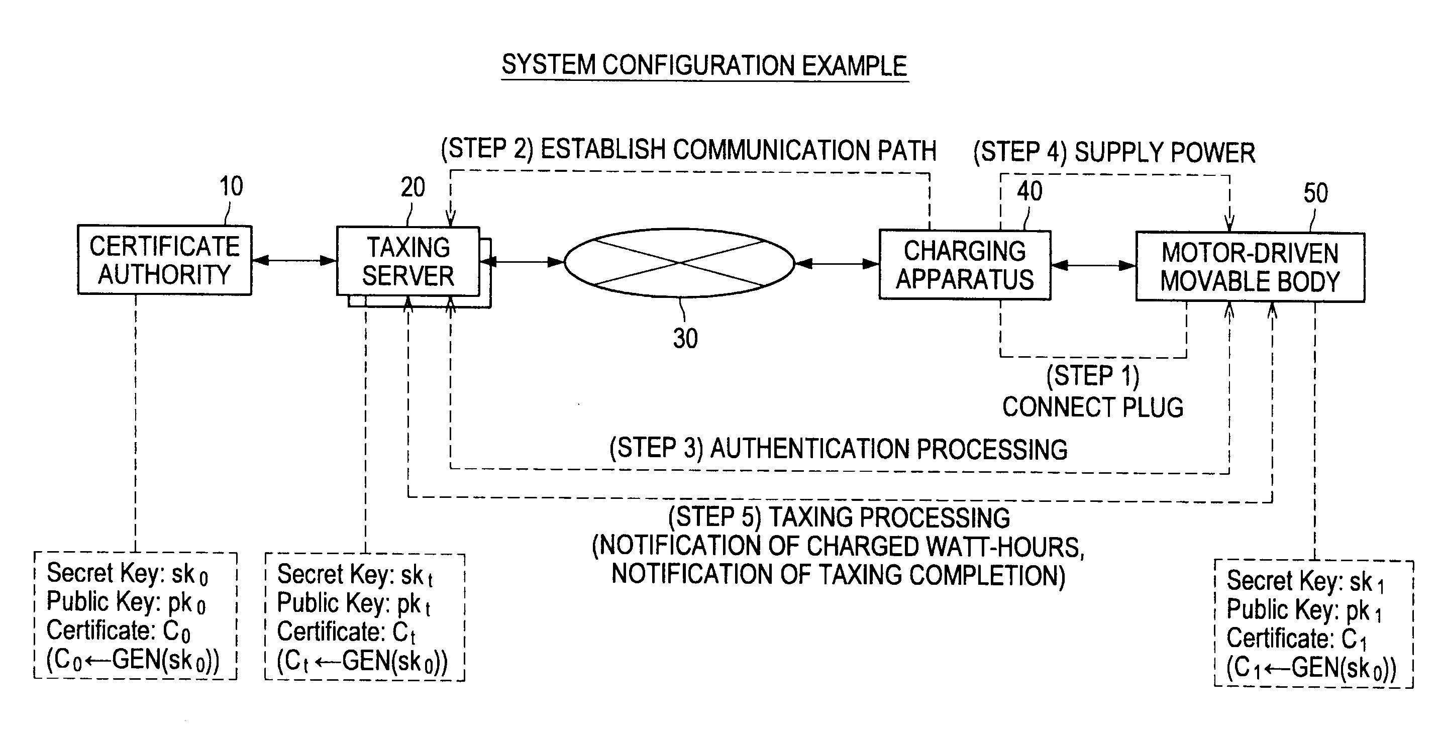
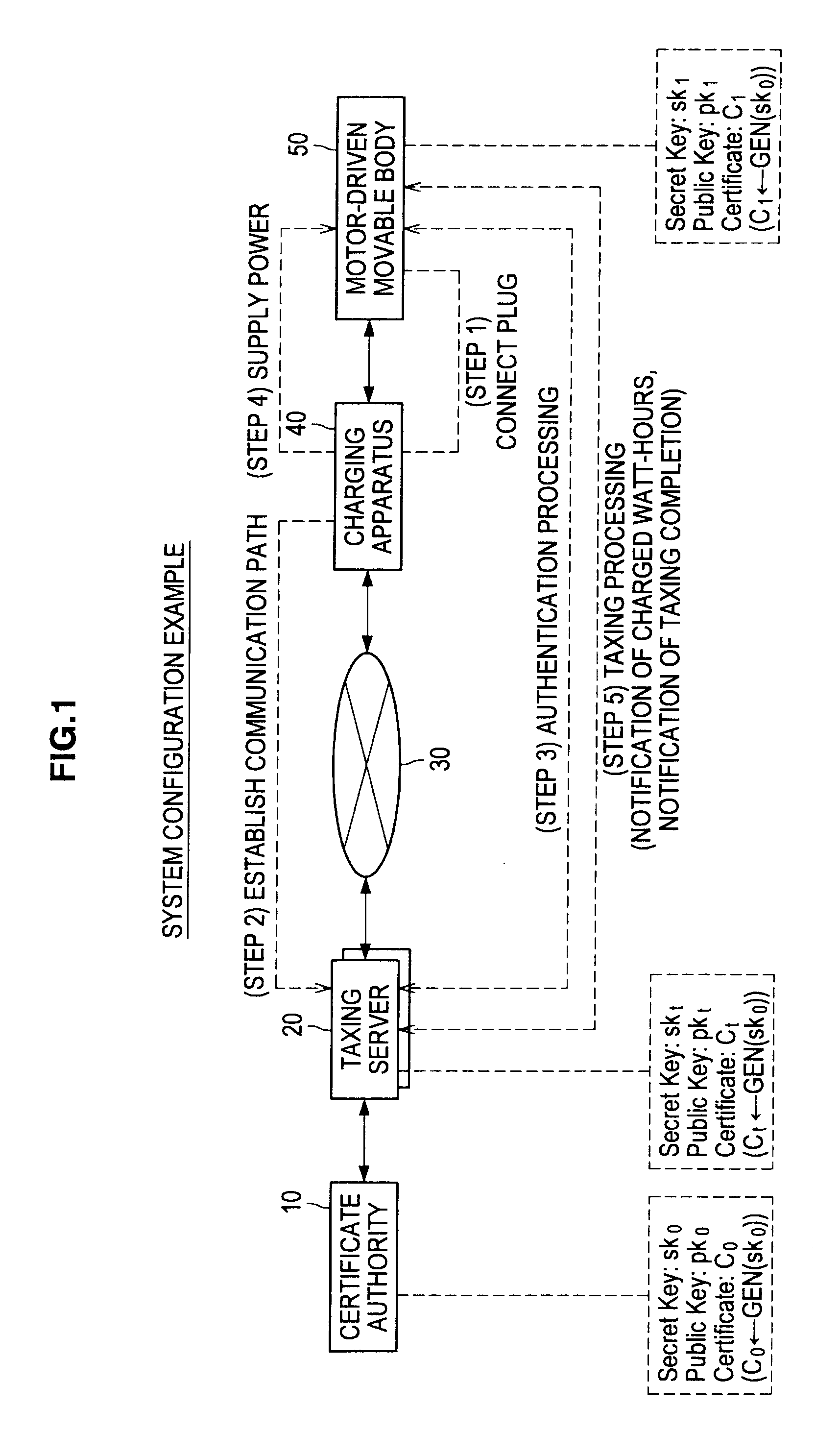
[0059]An embodiment of the present invention will be described below. The present embodiment relates to a mechanism to securely and reliably collect taxes imposed while an electric vehicle is charged. Particularly, the present embodiment relates to a charging system capable of reliably imposing taxes specific to an electric vehicle on the owner of the electric vehicle without providing a dedicated outlet to charge the electric vehicle.

1-1: Overall Configuration of Charging System

[0060]First, the overall configuration of a charging system according to the present embodiment will be described with reference to FIG. 1. FIG. 1 is an explanatory view showing a system configuration example of a charging system according to the present embodiment and the flow of taxing processing performed in the charging system during charging. The system configuration of the charging system shown in FIG. 1 is only an example and the system configuration can arbitrarily be modified in a range...


PUM


Abstract

An electronic device that includes an interface that connects to a charging apparatus and exchanges authentication information with a server via a network. The electronic device also includes a control unit that controls charging of a battery of the electronic device based on power received from the charging apparatus. Upon completion of the charging operation, the interface of the electronic device transmits information for calculating a tax based on the charging operation to the server.

Description

CROSS REFERENCE TO RELATED APPLICATION[0001]This application claims the benefit of priority under 35 U.S.C. §119 from Japanese Priority Patent Application JP 2009-285441 filed in the Japan Patent Office on Dec. 16, 2009, the entire contents of which is hereby incorporated by reference.BACKGROUND OF THE INVENTION[0002]1. Field of the Invention[0003]The present invention relates to a electric vehicle, a taxing server, a charging apparatus, a drive management method, and a program.[0004]2. Description of the Related Art[0005]In recent years, a technology called a smart grid has gained attention. The smart grid is a technical framework to realize efficient power usage by constructing a new transmission network having a communication channel along with the transmission network and using the intelligent transmission network. The idea of the smart grid, as a background, is to realize efficient management of power usage, swift handling of an incident when such an incident occurs, remote con...

Claims


Application Information

Patent Timeline
IPC IPC(8): G06F7/00G06F17/00B60L11/18G06Q50/00G06Q50/26H02J7/00H04L9/32
CPCB60L11/1824Y02T90/121B60L11/1846B60L11/1848B60L2210/20G06Q20/145G06Q50/06G07F15/003G07F15/005H02J7/04H02J2007/0001Y02T10/7005Y02T10/7088Y02T10/725Y02T90/127Y02T90/128Y02T90/14Y02T90/163Y02T90/169Y04S30/14H04L63/08B60L11/1838Y02T10/7072B60L53/65B60L53/665H02J7/00045B60L53/68B60L53/66B60L53/305H02J7/007Y02T10/70Y02T10/72Y02T90/12Y02T90/16Y02T90/167
Inventor ISHIBASHI, YOSHIHITO
Owner SONY CORP
Why Eureka
Try Eureka