
Scalable apparatus and method for increasing throughput in multiple level minimum logic networks using a plurality of control lines

a logic network and control line technology, applied in the field of multi-level interconnection structure, can solve the problem that the reed patent cannot accept simultaneous input messages

Inactive Publication Date: 2007-05-22
INTERACTIC HLDG LLC
View PDF12 Cites 24 Cited by
  • Summary
  • Abstract
  • Description
  • Claims
  • Application Information

AI Technical Summary

Benefits of technology

[0017]It is therefore our object of the present invention to provide a high throughput, low-latency interconnect structure which utilizes the advantages of the Reed Patent and the Hesse Patent while achieving improvements over their teachings.

Problems solved by technology

However, in the Reed Patent, there was available only one unblocked node to where an incoming message could be sent so that in practice the nodes in the Reed Patent could not accept simultaneous input messages.

Method used


Image

  • Scalable apparatus and method for increasing throughput in multiple level minimum logic networks using a plurality of control lines
  • Scalable apparatus and method for increasing throughput in multiple level minimum logic networks using a plurality of control lines
  • Scalable apparatus and method for increasing throughput in multiple level minimum logic networks using a plurality of control lines

Examples


first embodiment

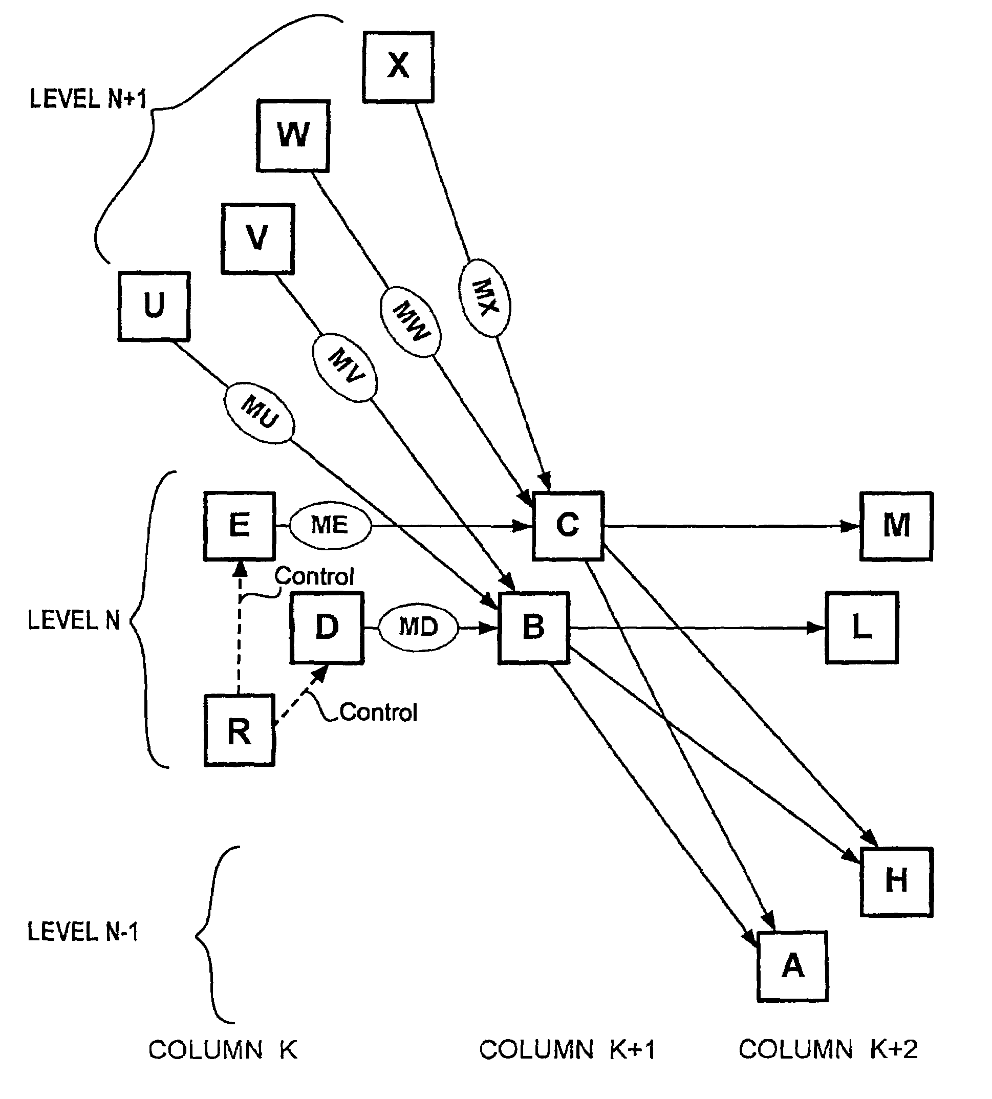
[0041]FIG. 4 illustrates the present invention.

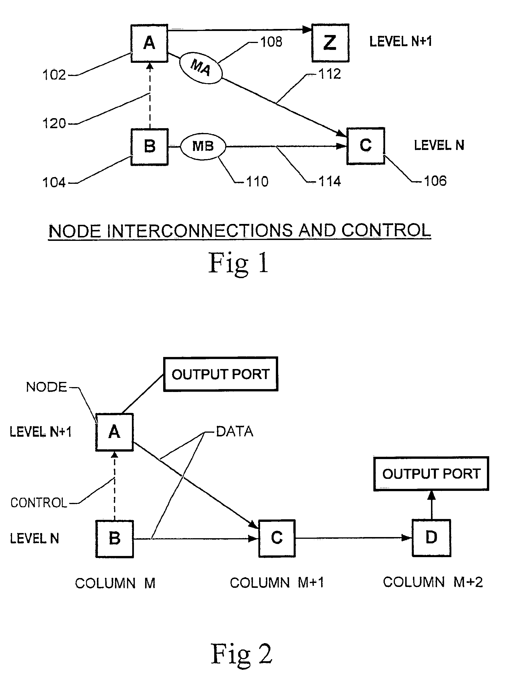
[0042]Five nodes are illustrated in FIG. 4. In addition to the four nodes shown in FIG. 2, there is a node H on level N-1. Node C is capable of sending data to node H. When node B sends a message MB to C and that message travels from C to H, then node A can send a message MA to C which will arrive at C simultaneously with the message MB. Message MA can then travel from C to D in the same time period that MB travels from C to H. The ability of a node to accept two messages at the same time is one advantage of the present invention, and is a novel improvement over the earlier Reed and Hesse patents.

[0043]Since there are no buffers at the node C, when two messages MA and MB arrive at C concurrently, one of the two messages must travel to H and one of the two messages must travel to D. In the present embodiment, MB is free to travel to H allowing MA to travel to D. In case the two messages MA and MB both travel to C, then the logic at C rou...


PUM


Abstract

A network or interconnect structure which includes a plurality of nodes which are interconnected within a hierarchical multiple level structure. The level of each node is determined by the position of the node within the structure and data messages move from node to node from a source level to a destination level. Each node within the interconnect structure is capable of receiving simultaneous data messages at its input ports from any other node and the receiving node is able to transmit each of the received data messages through its output ports to separate nodes in the interconnect structure to one or more levels below the level of the receiving node.

Description

RELATED PATENTS AND APPLICATIONS[0001]This application is related to U.S. patent application Ser. No. 09 / 009,703, filed on Jan. 20, 1998, which is pending and is incorporated by reference in its entirety. This application is also related to and incorporates U.S. Pat. No. 5,996,020, herein by reference in its entirety.[0002]The disclosed system and operating method are related to subject matter disclosed in the following co-pending patent applications that are incorporated herein in their entirety:[0003]1. U.S. patent application Ser. No. 09 / 693,359, entitled “Scaleable Multipath Wormhole Interconnect,” naming John Hesse as inventor, and filed on even date herewith.[0004]2. U.S. patent application Ser. No. 09 / 693,603, entitled “Scaleable Interconnect Structure for Parallel Computing and Parallel Memory Access, naming Coke Reed and John Hesse as inventors and filed on even date herewith.[0005]3. U.S. patent application Ser. No. 09 / 693,358, entitled “Scaleable Interconnect Structure Ut...

Claims


Application Information

Patent Timeline
Patent Type & Authority Patents(United States)
IPC IPC(8): H04L12/28G06F15/173H04L12/50H04L12/56H04Q3/00
CPCH04L45/30H04L49/15H04L45/00H04L45/04H04L45/06G01R31/08
Inventor REED, COKEHESSE, JOHN
Owner INTERACTIC HLDG LLC
Learn More