Real time tracking and monitoring of gas cylinders

Inactive Publication Date: 2011-06-16
MATHESON TRI GAS
View PDF22 Cites 55 Cited by
  • Summary
  • Abstract
  • Description
  • Claims
  • Application Information

AI Technical Summary

Benefits of technology

[0006]The methods and systems described may include automatic sharing of RFID generated location and consumption information with a gas supplier to estimate when replacement gas cylinders should be ordered and shipped to the end-user's facility. These methods and systems allow frequent or even continuous updates of gas inventories at an end-user's facility without a corresponding drain on worker resources. These processes can also significantly reduce the risk of logistical errors and misinterpretation of gas data that may result in a gas run-out, thus permitting the end user to purchase, stock, and utilize the optimum number of gas cylinder products.
[0007]Methods and systems are also described for tracking and locating individual gas cylinders using RFID technology within a gas producer's plant, a storage facility, or an end-user facility, among other sites. These methods and systems provide real time information to track the location of gas cylinders transported between a gas producer facility where the cylinders are filled and an end-user's facility where the cylinders are discharged for storage or use. Providin

Problems solved by technology

These methods and systems address the performance limitations RFID technology has had to track and monitor gas cylinders due to signal attenuation problems when the RFID transceivers are in close proximity to metal cylinder parts.
Providing gas cylinder location information in real time reduces the opportunities

Method used


Image

  • Real time tracking and monitoring of gas cylinders
  • Real time tracking and monitoring of gas cylinders
  • Real time tracking and monitoring of gas cylinders

Examples


Example

[0031]Through the application of specialized sensor technology and supporting system hardware installed on pressurized gas containers within an active RFID technology environment, the acquisition of gas consumption data (and other gas attributes) can be facilitated and utilized for providing solutions to reducing supply chain management costs associated with purchasing pressurized gas containers including, but not limited to, order processing, delivery, manual labor and the acquisition and storage of gas products. Examples of methods, systems and equipment include:

Exemplary Gas Cylinder Transport Caps

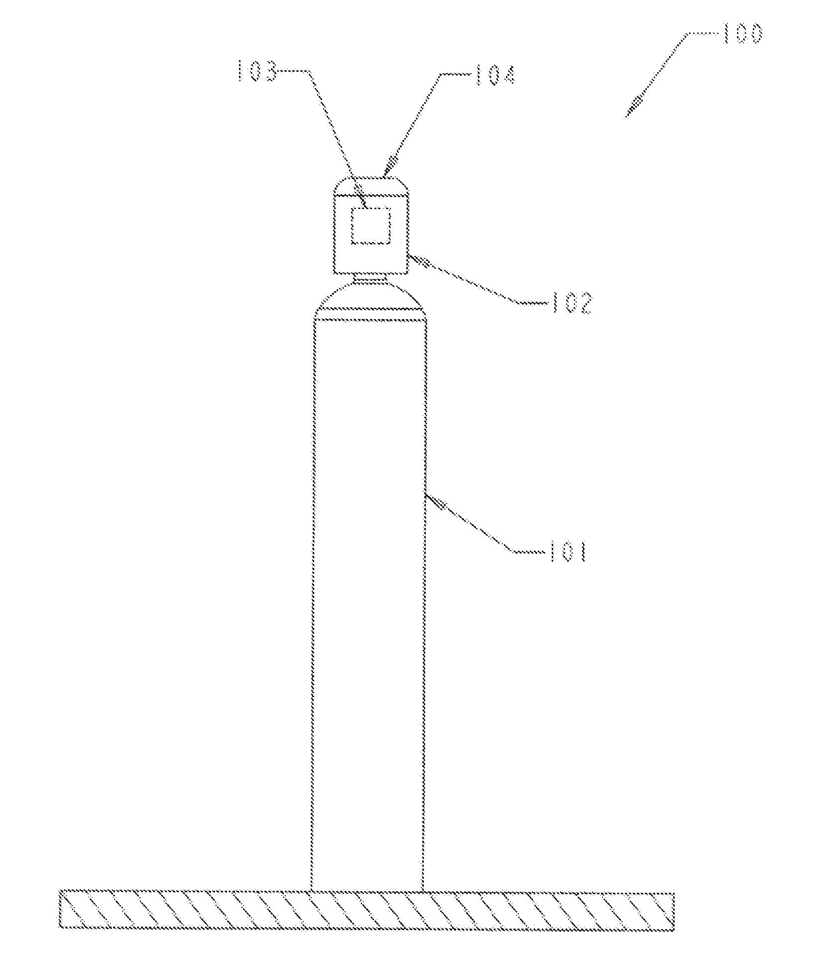
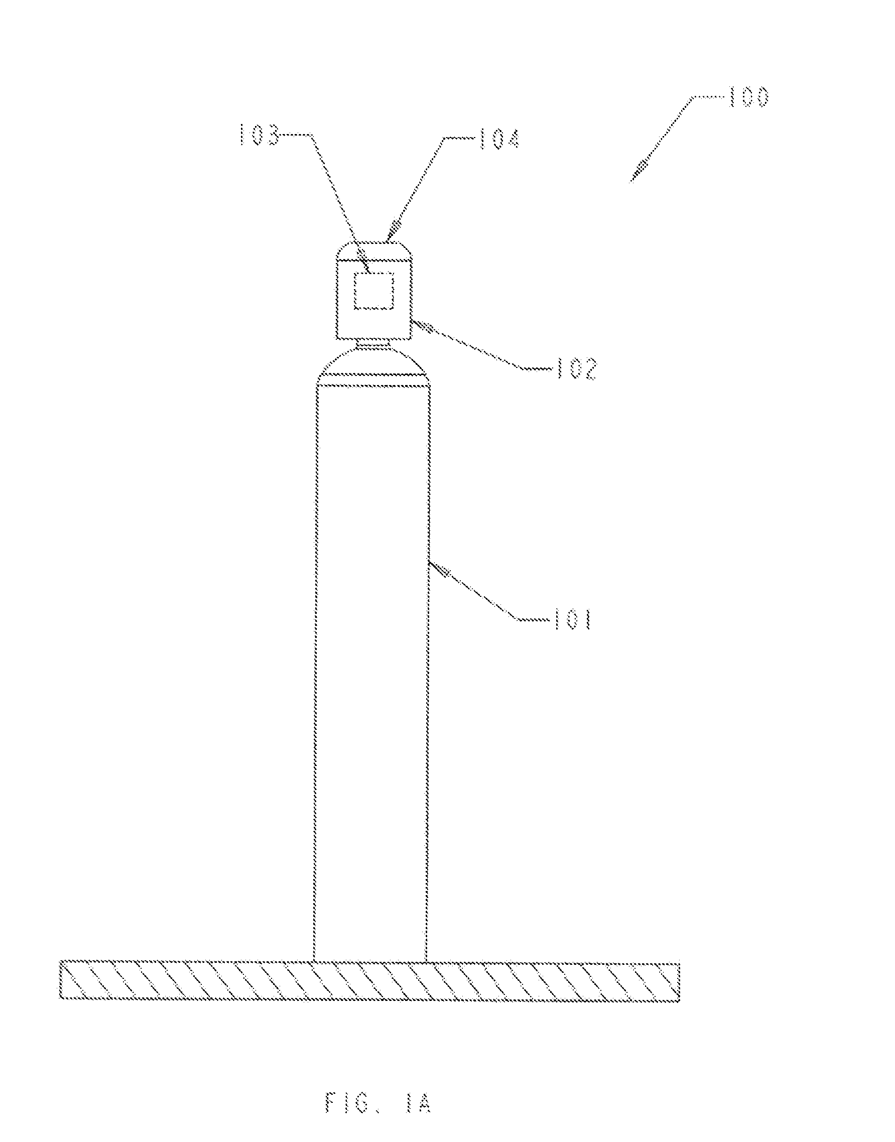
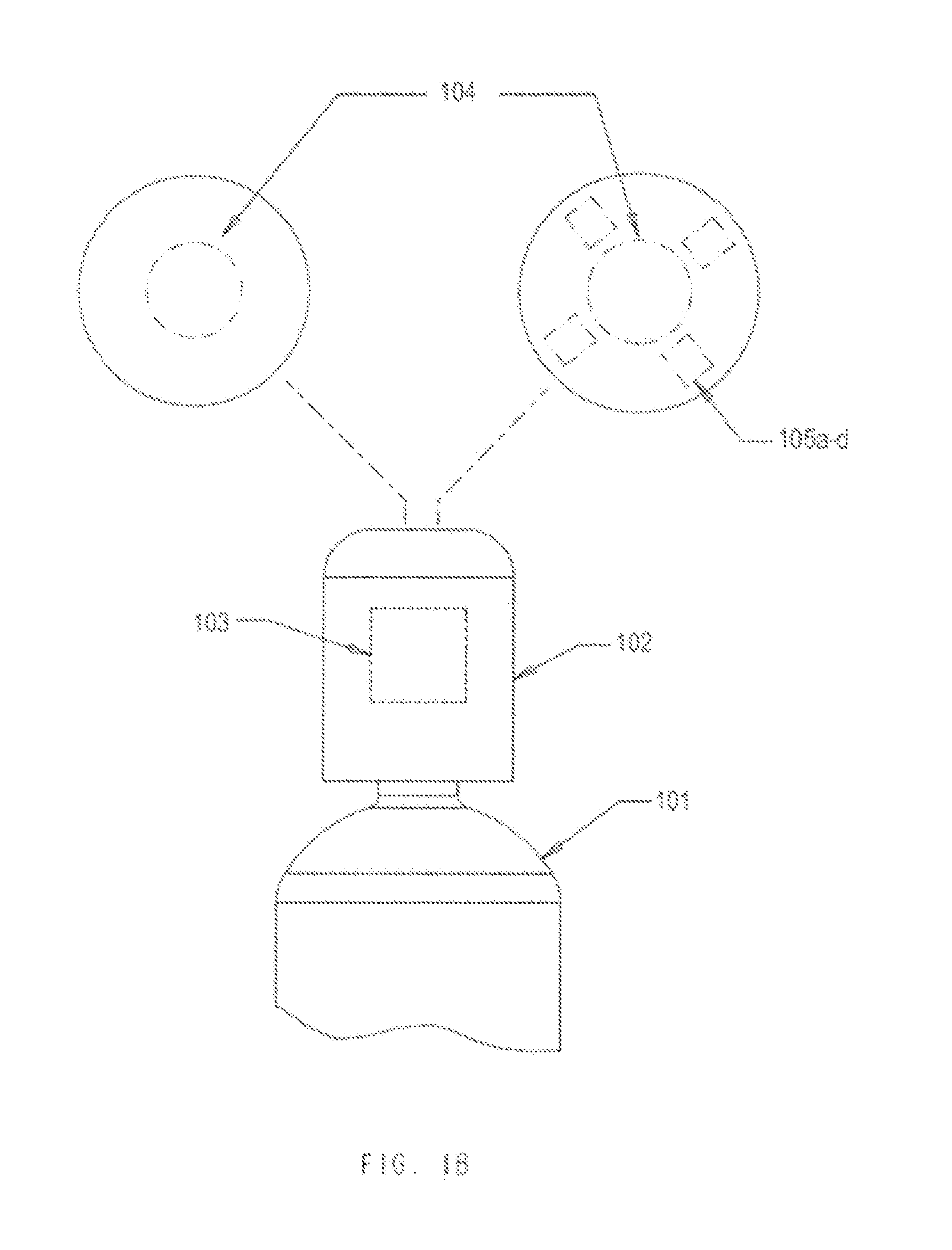
[0032]FIGS. 1A-B show a gas storage and monitoring system 100 that includes a gas cylinder transport cap 102 that is designed to maintain steady-state RFID signal propagation from an integrated RFID device 103 located inside cap 102 when it is secured to the top of gas cylinder 101. As shown in FIG. 1B, the top of the transport cap 104 may include one or more openings that reduce electr...


PUM


Abstract

A gas cylinder transport cap is described. The cap has a bottom opening adapted for reversible attachment to a gas cylinder, where the attached cap surrounds a cylinder valve coupled to the gas cylinder. The cap also has a side surface which at least in part defines the perimeter of the bottom opening, where the side surface include a plurality of side openings; and a top surface formed on an opposite side of the cap from the bottom surface, where the top surface includes a top opening. The side openings and top opening improve transmissions of radio-frequency signals from a RFID device positioned inside the cylinder cap when the cap is attached to the gas cylinder. A method of tracking a gas cylinder transported between a first and second location is also described. The method may include the steps of coupling the gas cylinder to a RFID device, loading the gas cylinder on a transportation vehicle, and reading a gas cylinder identification signal transmitted by the RFID device with an RFID signal reader that translates the signal into gas cylinder identification data. The gas cylinder identification data may be associated with location data provided by a GPS device located in the transportation vehicle. The identification and location data may be communicated to gas cylinder tracking system that is remote from the transportation vehicle.

Description

CROSS-REFERENCES TO RELATED APPLICATIONS[0001]This application is a nonprovisional of, and claims the benefit of the filing date of U.S. Provisional Patent Application No. 61 / 286,992, entitled “REAL TIME TRACKING AND MONITORING OF GAS CYLINDERS,” filed Dec. 16, 2009, the entire disclosure of which is incorporated herein by reference for all purposes.BACKGROUND OF THE INVENTION[0002]Typically, the management of gas cylinder consumption within a manufacturing plant or a laboratory has been a manual process. Employees are tasked to identify the gas cylinders across a facility, transport them and also monitor the pressure for each gas cylinder attached to the device or process that consumes such gas. This manual process produces many inefficiencies, including lost cylinders, and lost time spent locating misplaced cylinders. But perhaps the greatest inefficiency occurs when a logistical breakdown results in a gas run-out during a lab experiment or as part of a manufacturing process. Thes...

Claims


Application Information

Patent Timeline
IPC IPC(8): G06K7/01B65D25/00G08B5/22G01L7/00
CPCF17C13/021F17C13/003F17C13/025F17C13/026F17C2201/0109F17C2201/0119F17C2201/032F17C2201/056F17C2201/058F17C2203/0617F17C2205/0107F17C2205/0142F17C2205/0157F17C2205/0308F17C2205/058F17C2250/0408F17C2250/0421F17C2250/043F17C2250/0439F17C2250/0478F17C2250/0491F17C2270/0745F17C13/023
Inventor WASSEL, KEVIN A.COUGHLIN, EDWARD R.
Owner MATHESON TRI GAS
Why Eureka
Try Eureka