Container for use in pneumatic transport system

a technology of pneumatic transport system and container, which is applied in the direction of container decorations, packaging, level indications, etc., can solve the problems of label scuffing, label shifting out of position on the outside bottle wall, and many prescription products that do not lend themselves to such handling

Inactive Publication Date: 2011-06-16
TENSION INT
View PDF13 Cites 17 Cited by
  • Summary
  • Abstract
  • Description
  • Claims
  • Application Information

AI Technical Summary

Benefits of technology

[0007]In a pneumatic container transport system, specialized cylindrical containers move between processing stations through cylindrical conduits propelled by low-pressure, high-velocity air. Annular ridges around the circumference of the containers minimize contact with the inside conduit walls and deter scuffing of labels which carry machine-readable indicia upon which the container transport system relies for directing the containers. In a preferred embodiment, the containers are bottles having a coaxial mouth closed by threaded caps, the caps preferably also include a transparent window to allow visual and spectroscopy analysis of the bottle contents. In an alternate embodiment, the containers are longitudinally symmetrical clamshells for irregularly shaped objects, the clamshells opening through a longitudinal mouth along one side and sealable with tamper-proof labels. In both embodiments, one end of the container may include a recess adapted to receive a RFID device in lieu of the machine-readable indicia on the labels.

Problems solved by technology

Such bottles necessarily engage the inside walls of such conduits, especially when rounding corners, and they abruptly may stop when reaching their destination.
Not only can their labels become scuffed from contact with conduit walls, but the labels can shift out of position on the outside bottle walls due to abrupt stopping.
Though prescription filling systems can be largely automated by standardizing prescription containers, labeling, certification, packaging and shipping, many prescription products do not lend themselves to such handling.

Method used


Image

  • Container for use in pneumatic transport system
  • Container for use in pneumatic transport system
  • Container for use in pneumatic transport system

Examples


Embodiment Construction

[0017]NOTE: hereinafter, the present invention is discussed in the context of a container transport system dedicated to filling pharmaceutical prescriptions, primarily into prescription bottles for most pill and capsule-like pharmaceuticals, or into clamshell containers for irregular objects. One having ordinary skill in the art will recognize that other types of containers having similar features may be substituted and still considered to be within the spirit and scope of the present invention.

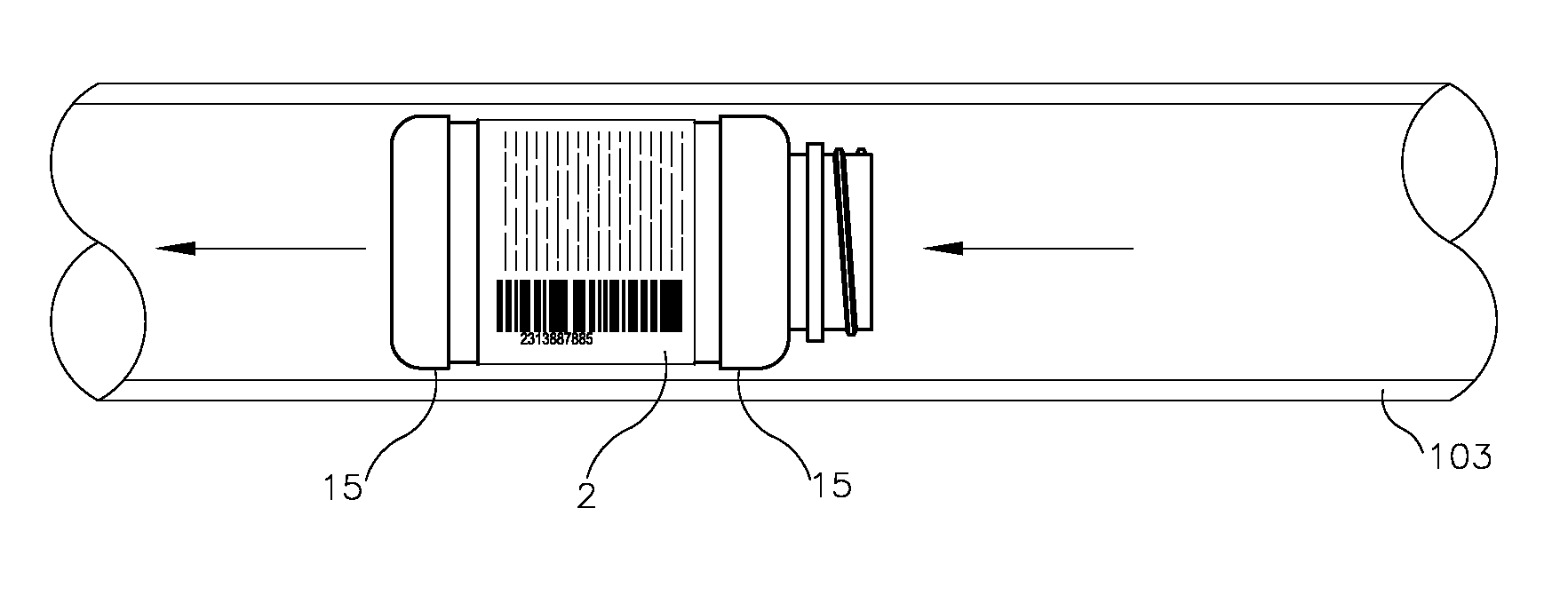
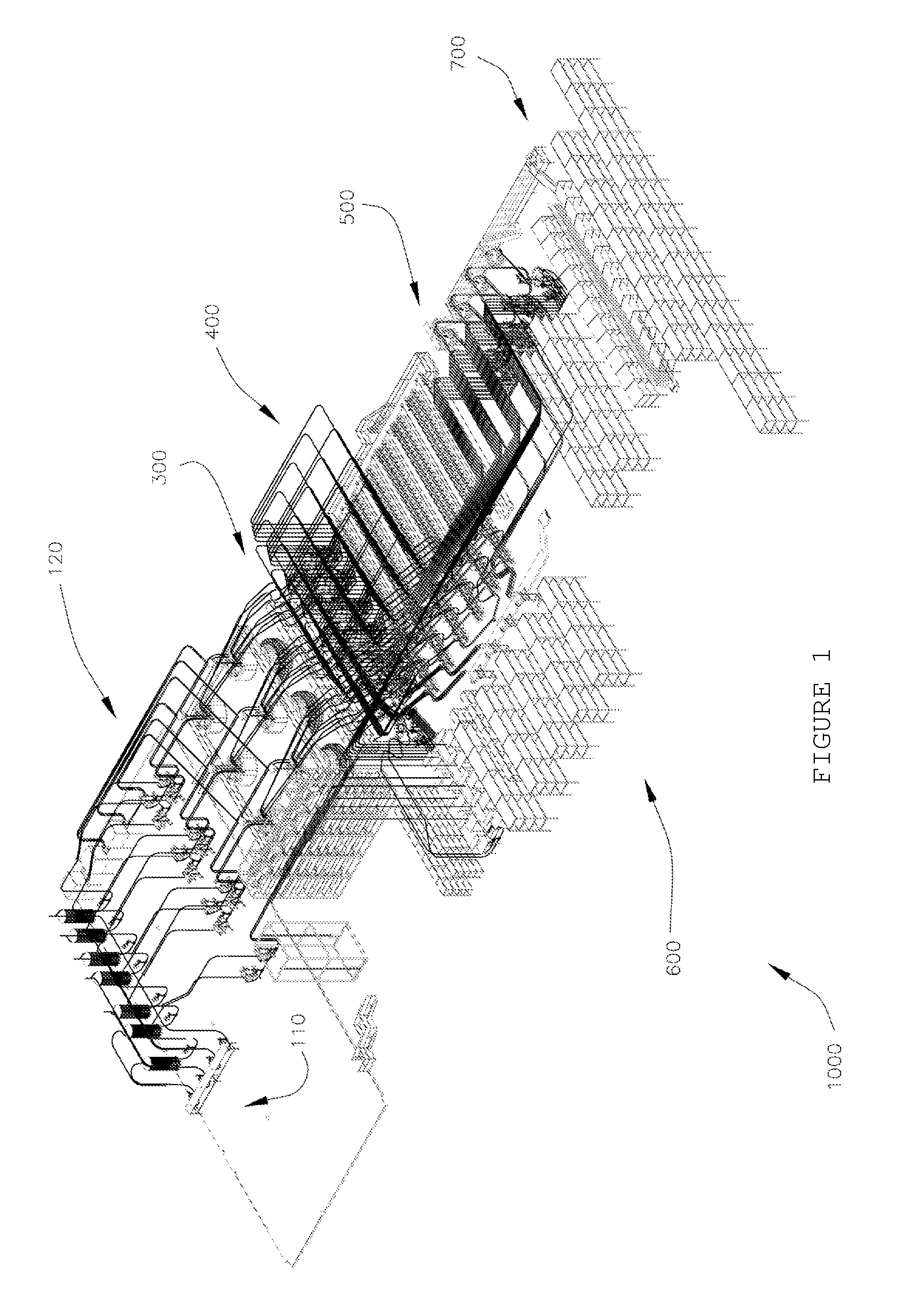
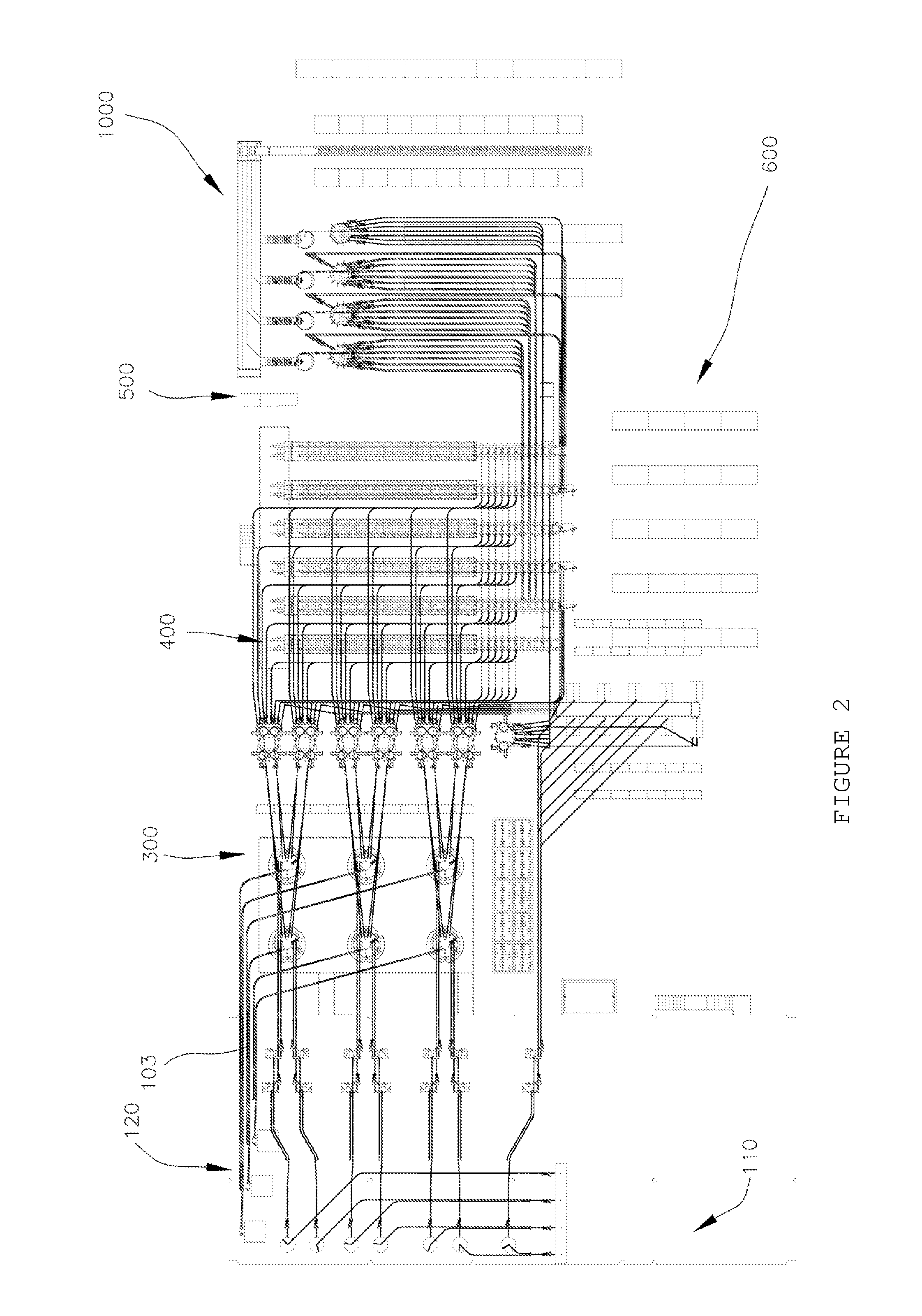
[0018]Referring now to the figures, and particularly to FIGS. 1-3, automated prescription filling system 1000 comprises prescription dispensing apparatus 300 feeding filled prescription bottles 10 (see FIG. 4A-4D) through prescription verification stage 400 and sortation conveyor system 500 to bagging, packaging and shipping system 600 where filled prescriptions are conveyed through common carriers to pharmacies, hospitals and individual patients (collectively “customers”). Apparatus 300 comp...


PUM


Abstract

In a pneumatic container transport system, specialized cylindrical containers move between processing stations through cylindrica conduits propelled by low-pressure, high-velocity air. Annular ridges around the circumference of the containers minimize contact with the inside conduit walls and deter scuffing of labels which carry machine-readable indicia upon which the container transport system relies for directing the containers. In a preferred embodiment, the containers are bottles having a coaxial mouth closed by threaded caps, the caps still preferably including a transparent window to allow visual and spectroscopy analysis of the bottle contents. In an alternate embodiment, the containers are longitudinally symmetrical clamshells for irregularly shaped objects, the clamshells opening through a longitudinal mouth along one side and sealable with tamper-proof labels.

Description

[0001]of which the following is a specification. This application is a continuation-in-part of, and claims priority to, a U.S. Provisional Application Ser. No. 61 / 090,900, filed Aug. 22, 2008. This application also claims priority to U.S. Provisional Application Ser. No. 61 / 112,776, filed Nov. 10, 2008.BACKGROUND OF THE INVENTION[0002]1. Field of the Invention[0003]This invention relates generally to automated pharmaceutical distribution systems and particularly to container transport systems for use in prescription filling systems. More particularly, this invention relates to a container for transporting small objects through tubing from one station to another through a pneumatic transport system.[0004]2. Description of Related Art[0005]In automated prescription filling systems, bottle handling requires transporting the bottles while tracking their exact location and status. In a preferred system, individually labeled prescription bottles move through pneumatic conduit or tubing im...

Claims


Application Information

Patent Timeline
Patent Type & Authority Applications(United States)
IPC IPC(8): B65G51/04
CPCB65G51/06B65D2203/02
Inventor TERZINI, ROBERT
Owner TENSION INT
Why Eureka
Try Eureka