
Overspeed protection system and method

a wind turbine and protection system technology, applied in the direction of rotors, marine propulsion, vessel construction, etc., can solve the problems of inefficient wind turbine operation, underutilized power generation capacity of wind turbines, and the maximum rotational speed of wind turbines, so as to prevent an overspeed condition of wind turbines

Inactive Publication Date: 2011-06-16
GENERAL ELECTRIC CO
View PDF15 Cites 27 Cited by
  • Summary
  • Abstract
  • Description
  • Claims
  • Application Information

AI Technical Summary

Benefits of technology

[0010]According to another embodiment, a method for preventing an overspeed condition of a wind turbine includes measuring a rotational speed of a hub of the wind turbine; comparing the measured rotational speed with a predetermined threshold value; if the measured rotational speed exceeds the threshold value, operating an auxiliary pitch drive controller independent of a main turbine controller so that a pitch angle of at least one rotor blade of the wind turbine is adjusted to effect aerodynamic braking of the wind turbine.

Problems solved by technology

Each electrical and / or mechanical component may have independent or different operating limitations, such as current, voltage, power, and / or temperature limits, than other components.
Moreover, known wind turbines typically are designed and / or assembled with predefined rated power limits.
Such operation may result in inefficient wind turbine operation, and a power generation capability of the wind turbine may be underutilized.
A particular operating limitation of a wind turbine is a maximum rotational speed of the wind rotor.
For larger wind turbine, the rotor may not be stopped by mechanical rotor brakes alone since the torque generated from the wind is too high.
Thus, the internal friction and the electrical load from the generator will slow down the rotor speed of the wind turbine.

Method used


Image

  • Overspeed protection system and method
  • Overspeed protection system and method
  • Overspeed protection system and method

Examples


Embodiment Construction

[0020]Reference will now be made in detail to the various embodiments, one or more examples of which are illustrated in each figure. Each example is provided by way of explanation and is not meant as a limitation. For example, features illustrated or described as part of one embodiment can be used on or in conjunction with other embodiments to yield yet further embodiments. It is intended that the present disclosure includes such modifications and variations.

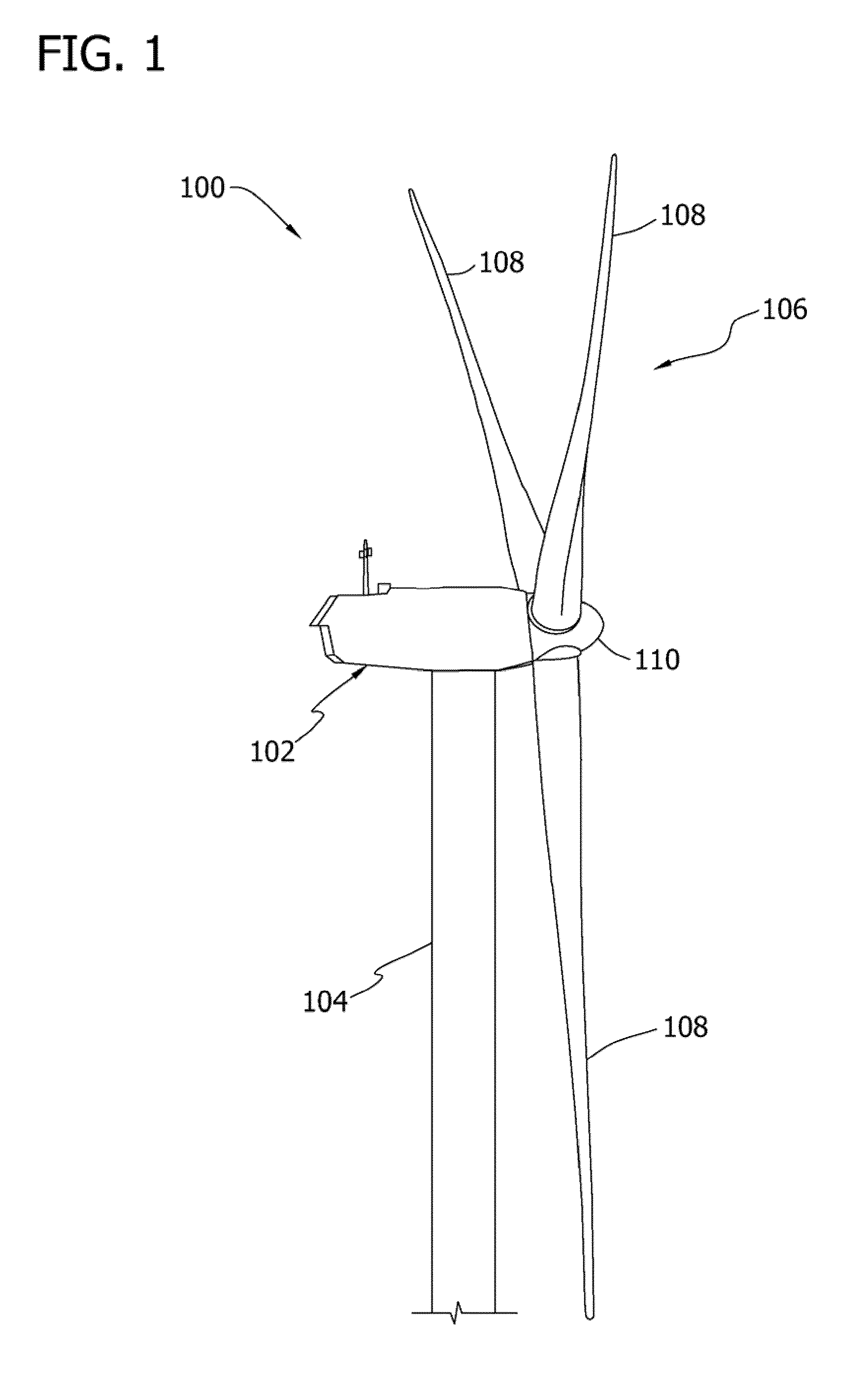
[0021]As used herein, the term “blade” is intended to be representative of any device that provides a reactive force when in motion relative to a surrounding fluid. As used herein, the term “wind turbine” is intended to be representative of any device that generates rotational energy from wind energy, and more specifically, converts kinetic energy of wind into mechanical energy. As used herein, the term “wind generator” is intended to be representative of any wind turbine that generates electrical power from rotational energy ge...


PUM


Abstract

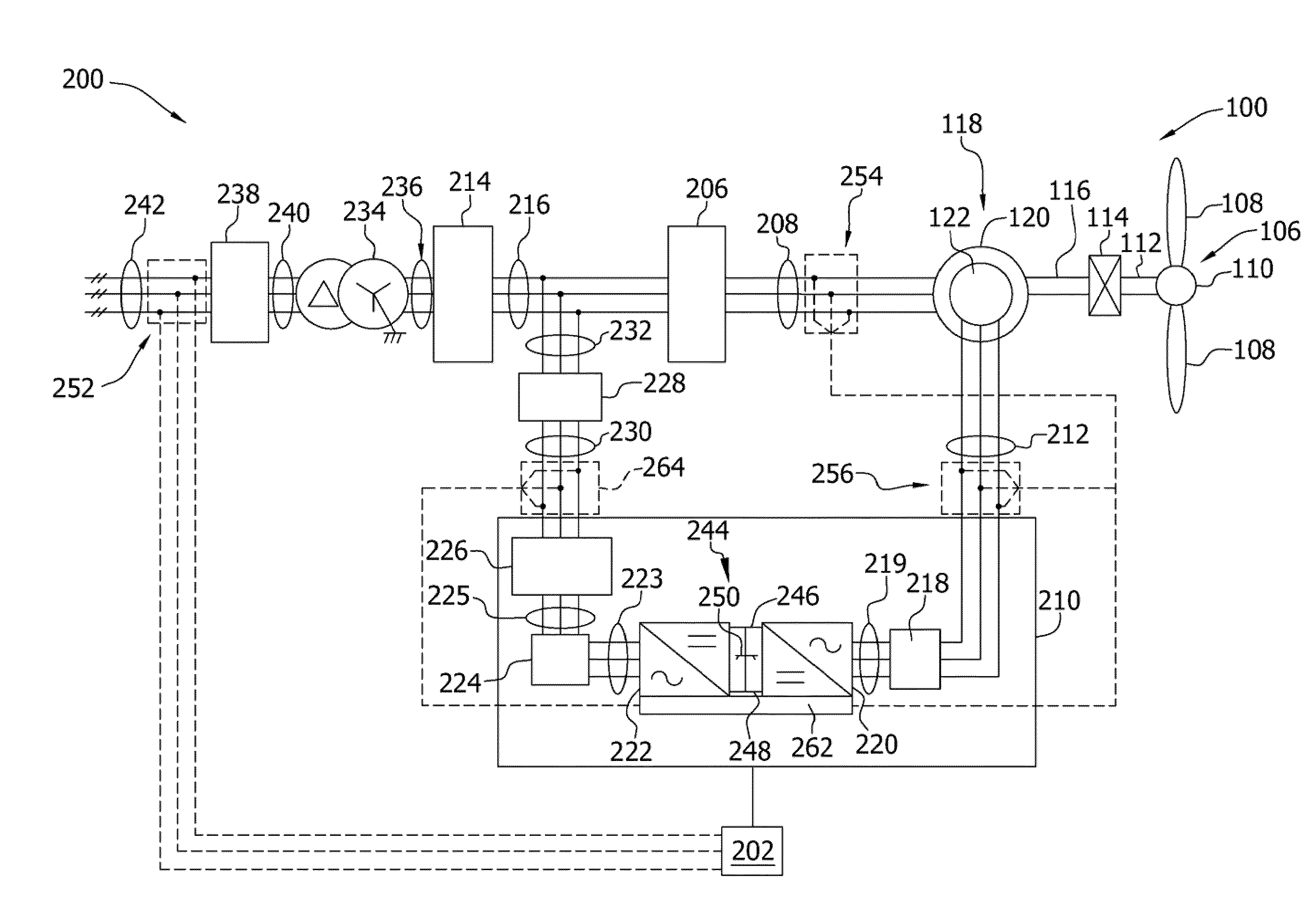
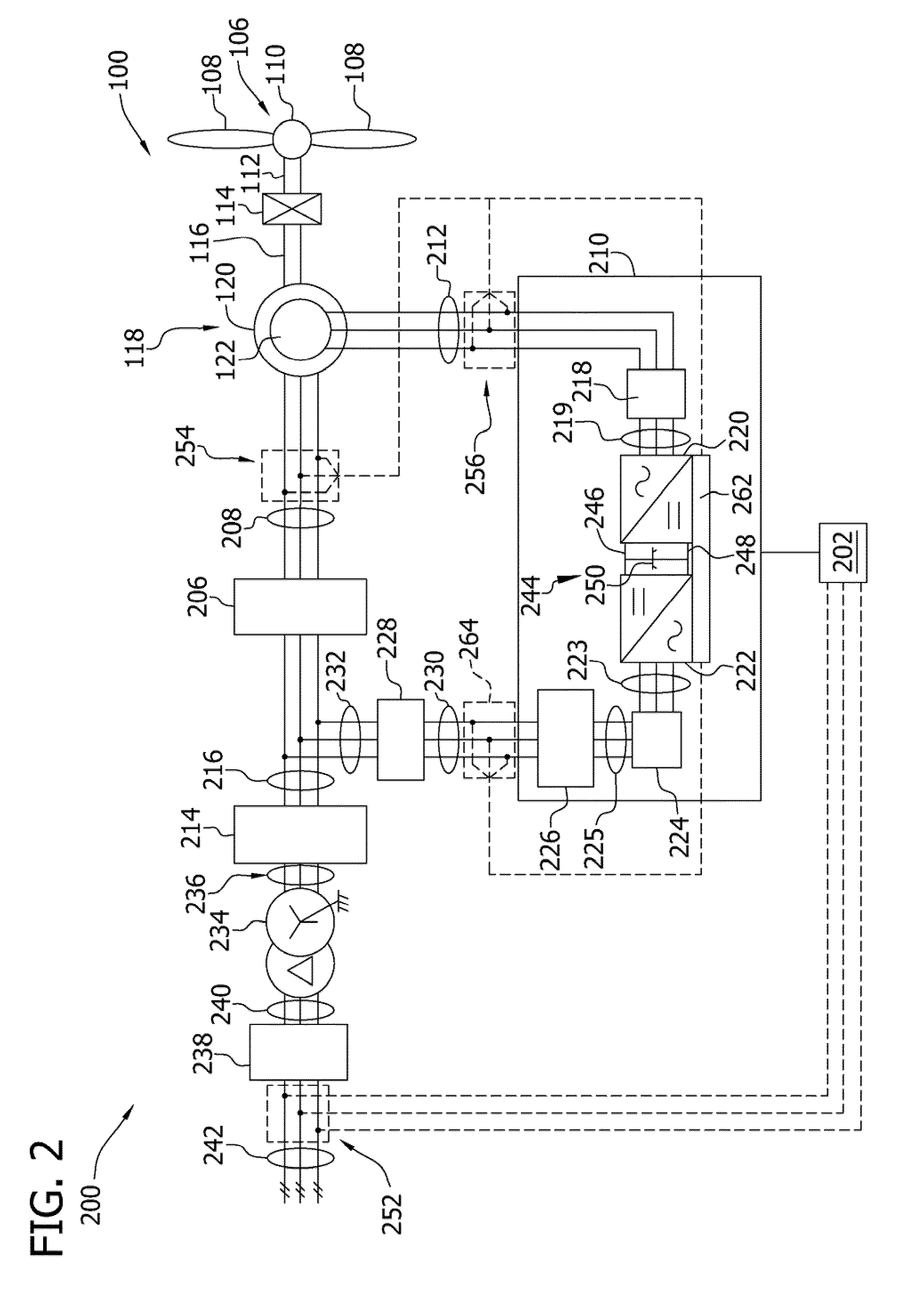
An overspeed protection system for a wind turbine having a hub and at least one rotor blade mounted to the hub includes a rotation sensor adapted for measuring a rotor speed of said wind turbine; a comparator connected to the rotation sensor and adapted for comparing the measured rotor speed with a predetermined threshold value of the rotor speed wherein the comparator outputs a signal indicative of the comparison; and an auxiliary pitch drive controller connected to the comparator and adapted to receive the signal indicative of the comparison, the auxiliary pitch drive controller being further adapted for controlling a pitch drive unit of the wind turbine independently of a main turbine controller and, if the threshold value is exceeded, to adjust a pitch angle of the rotor blade of the wind turbine so that aerodynamic braking of the wind turbine is effected.

Description

BACKGROUND OF THE INVENTION[0001]The subject matter described herein relates generally to methods and systems for controlling the operation of a wind turbine, and more particularly, to methods and systems for preventing an overspeed condition of a wind turbine.[0002]Generally, a wind turbine includes a turbine that has a rotor that includes a rotatable hub assembly having multiple blades. The blades transform wind energy into a mechanical rotational torque that drives one or more generators via the rotor. The generators are sometimes, but not always, rotationally coupled to the rotor through a gearbox. The gearbox steps up the inherently low rotational speed of the rotor for the generator to efficiently convert the rotational mechanical energy to electrical energy, which is fed into a utility grid via at least one electrical connection. Gearless direct drive wind turbines also exist. The rotor, generator, gearbox and other components are typically mounted within a housing, or nacell...

Claims


Application Information

Patent Timeline
IPC IPC(8): F04D29/18F04D27/00
CPCF03D7/0224F03D7/0252F03D7/0268Y02E10/723F05B2270/1011F05B2270/327F03D7/047Y02E10/72
Inventor MENKE, DETLEFLOH, FRIEDRICH
Owner GENERAL ELECTRIC CO
Learn More