Rotating blade system for a row of rotating blades of a turbomachine

a technology of rotating blades and turbomachines, which is applied in the direction of propellers, propulsive elements, water-acting propulsive elements, etc., can solve the problems of only being controlled, moving blade segments are mechanically decoupled from each other, and can no longer be braced, so as to increase the durability of the moving blade sequence and the continuous-flow machine as a whole, and save significant weight and cost. , the effect of reducing streaming losses

Inactive Publication Date: 2011-06-16
MTU AERO ENGINES GMBH
View PDF2 Cites 6 Cited by
  • Summary
  • Abstract
  • Description
  • Claims
  • Application Information

AI Technical Summary

Benefits of technology

[0017]In an additional advantageous embodiment of the invention provision is made that the moving blades sequence is disposed in a turbine area, particularly in a low-pressure turbine area of the continuous-flow machine. It is thereby possible to provide the continuous-flow machine with few moving blade sequences, whereby significant weight- and cost-savings arise. Due to the coupling of the moving blades with the shroud bands on the one hand and the coupling of the at least two moving blade segments with one another on the other, the number of joints and gaps in the moving blade sequence is reduced, whereby possible streaming losses are correspondingly reduced. In addition fewer surfaces of engagement present themselves to the aggressive hot gases that arise in the turbine area, whereby the durability of the moving blade sequence and the continuous-flow machine as a whole is increased.
[0018]A further aspect of the invention concerns a method for the mounting of a moving blade sequence for a continuous-flow machine, in particular for a thermal gas turbine in the case of which at least two moving blade segments of a moving blade system are provided according to one of the previous embodiment examples and those moving blades of the at least two moving blade segments, which are respectively tilted axially by an angle (αa, αb) relative to their respective base inclination, are disposed in an adjacent manner to each other, wherein the angles in regard to the base inclination of the moving blades feature opposite signs. This permits a mechanically stable and oscillation-mechanics related non-critical mounting of the moving blade sequence, whereby a significant reduction of the manufacturing costs with at the same time increased durability is provided. An additional advantage is in the fact that the bracing contact forces between the moving blade segments only appear, depending on the number of revolutions, during the operation of the continuous-flow machine so that the moving blade segments are particularly easily mounted or dismantled during standstill.

Problems solved by technology

The circumstance is however viewed as a disadvantage in the known moving blade systems that the moving blade segments, in contrast to moving blade systems made of individual moving blades, can no longer be braced by means of the torsion of the moving blades of a moving blade sequence against one another.
As a result the moving blade segments are mechanically decoupled from one another and can only be controlled with difficulty from an oscillation-mechanics related point of view.

Method used


Image

  • Rotating blade system for a row of rotating blades of a turbomachine
  • Rotating blade system for a row of rotating blades of a turbomachine

Examples


Embodiment Construction

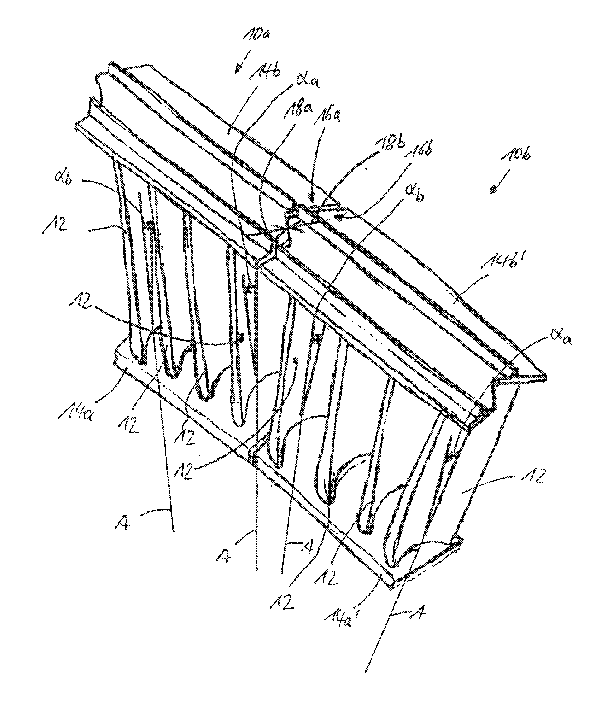
[0022]FIGURE. 1 shows a schematic perspective view of two moving blade segments 10a, 10b that are coupled to one another of a moving blade system that is implemented with a plurality of moving blade segments 10 for a moving blade sequence for the purpose of disposition in a low-pressure turbine area of a thermal gas turbine (not represented). Each moving blade segment 10a, 10b encompasses in the present embodiment example respectively four moving blades 12 (airfoils) that are disposed, in reference to a rotation axis of the moving blade sequence that is mounted in the continuous-flow machine, primarily radially between a radially interior shroud band 14a, 14a′ and a radially exterior shroud band 14b, 14b′ and are coupled to the shroud bands 14a, 14b or 14a′, 14b′. The radially exterior shroud bands 14b, 14b′ of the two moving blade segments 10a, 10b encompass contact surfaces 16a, 16b that are implemented in a manner corresponding to one another, with a Z-shaped course (so-called Z-...


PUM

PropertyMeasurementUnit
angles αaaaaaaaaaaa
angles αaaaaaaaaaaa
angles αaaaaaaaaaaa

Abstract

The invention concerns a moving blade system for a moving blade sequence of a continuous-flow machine, in particular a thermal gas turbine with at least two moving blade segments, of which each moving blade segment encompasses at least two moving blades that are disposed, in reference to a rotation axis of the moving blade sequence, at least primarily radially between a radially interior and a radially exterior shroud band and are coupled to the shroud bands, wherein at least the radially exterior shroud bands of the two moving blade segments encompass contact surfaces that correspond to one another, wherein radial equilibrium axes of neighboring moving blades of the at least two moving blade segments are disposed in a tilted manner by respectively axially an angle (60 a, αb) relative to their respective base inclination, wherein the angles (αa, αb) in regard to the base inclination feature opposite signs. The invention concerns furthermore a continuous-flow machine as well as a method for the mounting of a moving blade sequence for a continuous-flow machine.

Description

CROSS-REFERENCE TO RELATED APPLICATIONS[0001]This application is a U.S. National Phase application submitted under 35 U.S.C. §371 of Patent Cooperation Treaty application serial no. PCT / DE2009 / 001094, filed Aug. 1, 2009, and entitled ROTATING BLADE SYSTEM FOR A ROW OF ROTATING BLADES OF A TURBOMACHINE, which application claims priority to German patent application serial no. 10 2008 038 038.5, filed Aug. 16, 2008, and entitled LAUFSCHAUFELSYSTEM FUR EINE LAUFSCHAUFELREIHE EINER STROMUNGSMASCHINE.[0002]Patent Cooperation Treaty application serial no. PCT / DE2009 / 001094, published as WO 2010 / 020210, and German patent application serial no. 10 2008 038 038.5, are incorporated herein by reference.TECHNICAL FIELD[0003]The invention concerns a moving blade system for a moving blade sequence of a continuous-flow machine, e.g., a thermal gas turbine. The invention concerns furthermore a continuous-flow machine e.g., a thermal gas turbine, as well as a method for the mounting of a moving blad...

Claims


Application Information

Patent Timeline
Patent Type & Authority Applications(United States)
IPC IPC(8): F04D29/38B21K25/00
CPCY10T29/49321F05D2260/36F05D2250/314F05D2230/60F05D2260/96F01D5/225F05D2240/80F05D2250/31F01D5/16F05D2230/51
Inventor BOCK, ALEXANDER
Owner MTU AERO ENGINES GMBH
Why Eureka
Try Eureka