Structural bridging fastener

Inactive Publication Date: 2007-05-10
MULTIMATIC INC
View PDF37 Cites 0 Cited by
  • Summary
  • Abstract
  • Description
  • Claims
  • Application Information

AI Technical Summary

Benefits of technology

[0005] Accordingly, it would be advantageous to provide a simple, single-piece angle mounting bracket, capable of mounting a loaded subcomponent to a base structure, perpendicularly oriented to the main body of the mounting bracket, to provide an in-line configurati

Problems solved by technology

Structural stiffness and strength equivalent to a two-piece or “U” shaped mounting bracket can be realized with a sin

Method used


Image

  • Structural bridging fastener
  • Structural bridging fastener
  • Structural bridging fastener

Examples


Embodiment Construction

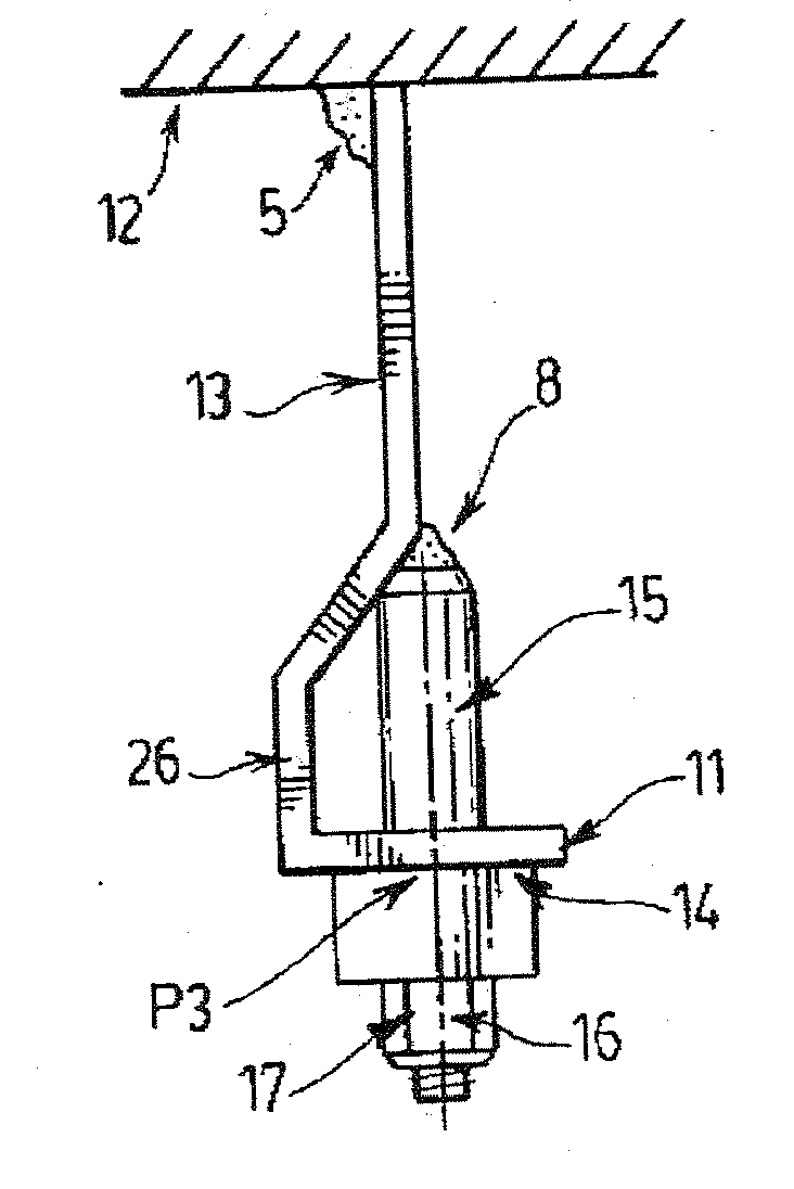
[0052]FIGS. 7 and 8 illustrate an angle mounting bracket (11) attached to abase structure (12) via welding, bonding, riveting, clinching, upset forming, bolting, or similar means, to form a joint (5). The angle mounting bracket (11) is configured with a substantially planar main body (13) and a mounting plate (14) oriented perpendicularly to the main body. A complex formation (26) allows the load point (P3) of the mounting plate (14) to be aligned directly with the axis of the substantially planar main body (13). In a first embodiment, at least one inventive fastening device (15) is fixed at the load point (P3) through a hole or orifice (7) in the mounting plate (14) of the mounting bracket via welding, bonding, riveting, clinching, upset forming, bolting, or similar means. As illustrated in FIGS. 7, 8 and 11A, the inventive fastening devices (15) include a threaded portion (19) protruding from the mounting plate (14). A loaded subcomponent (16) may be secured to the mounting plate ...


PUM


Abstract

A mounting bracket and structural bridging fastener comprises an angle mounting bracket attached to a stable base, the bracket comprising a substantially planar main body and a mounting plate oriented perpendicular to the main body, the mounting plate and main body being connected through a complex formation in the angle mounting bracket, a loaded subcomponent configured to be attached to the mounting bracket so that the attachment point of the loaded subcomponent is aligned directly with the main body, a fastener comprising a structural portion adapted to lie between and be rigidly fastened to the mounting plate and to the main body adjacent the complex formation, with the fastener further comprising a threaded portion adapted to connect the loaded subcomponent to the mounting plate. The threaded portion may be an extension of the structural portion adapted to receive a nut, or the threaded portion may be internal to the structural portion and adapted to receive a bolt. The mounting bracket and structural bridging fastener is particularly adapted to secure a vehicular steering column assembly to a vehicular cross-car instrument panel structure.

Description

FIELD OF THE INVENTION [0001] This invention relates to a threaded fastening device (fastener) configured to attach a loaded subcomponent to an angle mounting bracket while additionally enhancing the structural performance of the mounting bracket. Description of the Prior Art [0002] It is a common requirement to attach a loaded subcomponent (1) to a base structure (2) via a mounting bracket (3) as shown in prior art FIGS. 1 and 1A. Additionally, to facilitate ease of replacement, it is also common practice to attach the subcomponent (1) to the mounting bracket (3) via at least one threaded fastener (6) while the mounting bracket may be attached to the base structure via a wide range of methods that include welding, bonding, riveting, clinching, upset forming, bolting, or similar means, to form a joint (5). The mechanical fastening of the loaded subcomponent to the mounting bracket primarily relies on the threaded fasteners (6) generating sufficient clamping load between the subcompo...

Claims


Application Information

Patent Timeline
IPC IPC(8): A47F5/00E06B7/28
CPCB62D27/065
Inventor HOWELL, ROBERT
Owner MULTIMATIC INC
Why Eureka
Try Eureka