
Electronic bike integrated supplemental motor system

a motor system and electric bike technology, applied in the direction of electric devices, driver interactions, process and machine control, etc., can solve the problems of inability to efficiently recover surplus energy available from the user and/or the bicycle, difficulty in maintaining a steady pedal effort under varying load conditions, and prior art solutions that do not provide the capability to control a user's pedal effor

Inactive Publication Date: 2011-06-16
RUBEN MURRAY
View PDF2 Cites 36 Cited by
  • Summary
  • Abstract
  • Description
  • Claims
  • Application Information

AI Technical Summary

Problems solved by technology

Closed loop systems will respond to pedal effort, but not control that effort, making it difficult to maintain a steady pedal effort under varying load conditions.
Furthermore, most conventional motor controllers are more aggressive in their usage of battery energy because they are unable to efficiently recover surplus energy available from the user and / or the bicycle's stored kinetic and potential energy.
The prior art solutions do not provide any capability to control a user's pedal effort independently from the bicycle road speed.
All other known solutions do not directly manage the user's effort level.
This means the user has no direct control over their effort level, and the bike feels mushy when they attempt to pedal it while the motor is operating.
Without direct pedal effort control, it is difficult to manage the overall battery power consumption, speed, and the user's pedal effort level.
The consequence of less overall control is greater risk of fatigue or injury, and uncertainty in the allowable ride duration.
This generally leads to purchasing a larger battery with corresponding greater cost and weight penalties.
Failure to predict the battery capacity can lead to over-exertion, pedaling a potentially heavier than normal bicycle back home with an exhausted battery.

Method used


Image

  • Electronic bike integrated supplemental motor system
  • Electronic bike integrated supplemental motor system
  • Electronic bike integrated supplemental motor system

Examples


Embodiment Construction

[0019]The embodiments described herein disclose an improved battery operated electric motor and control system for a bicycle, tricycle or any similar human powered vehicle. Such vehicles are all referred to herein with the term e-bike. The motor and motor controller reduce or increase the user's pedal effort in a controlled manner which includes the ability to independently set and maintain the effort level while simultaneously managing the operating speed of the e-bike.

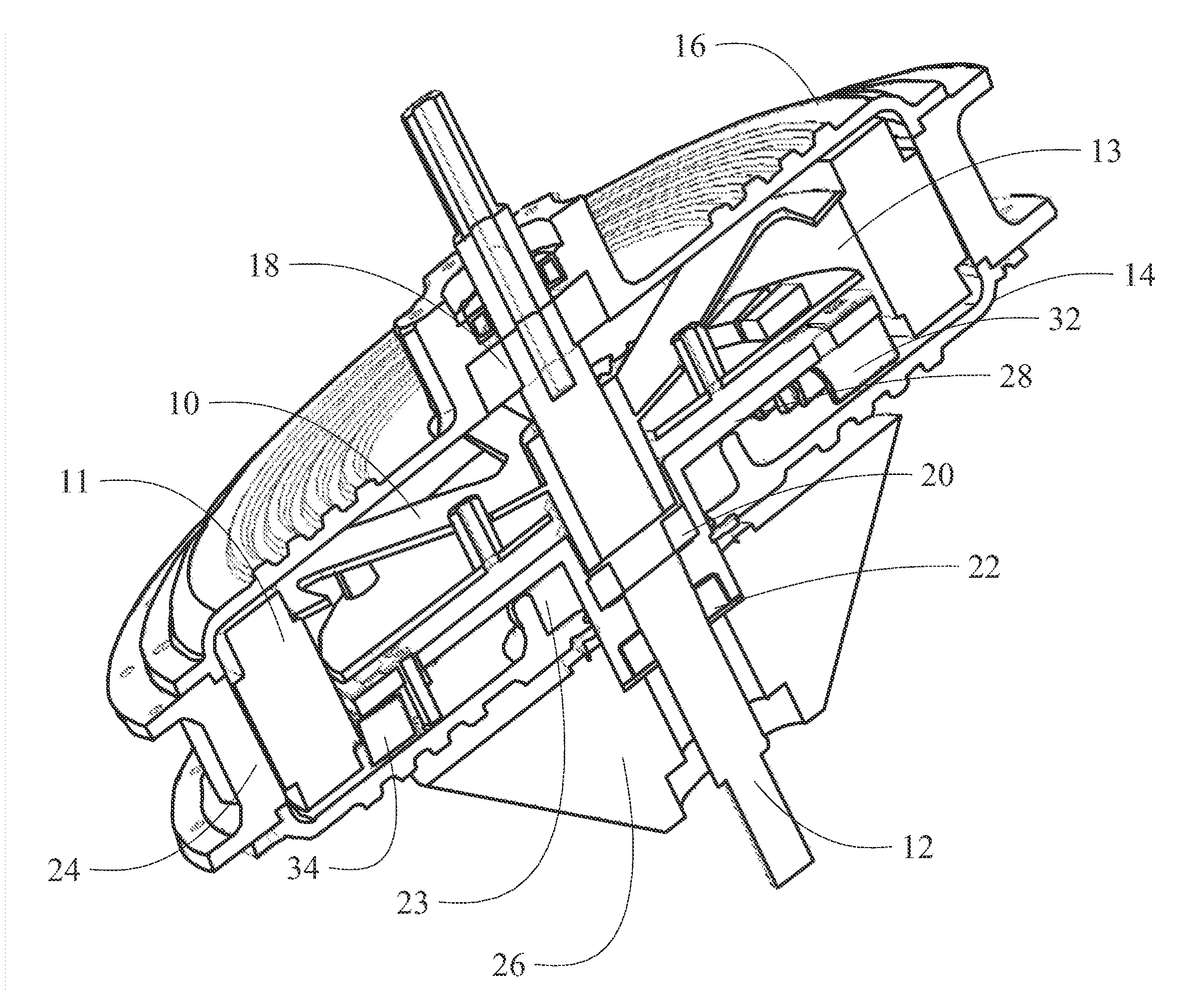
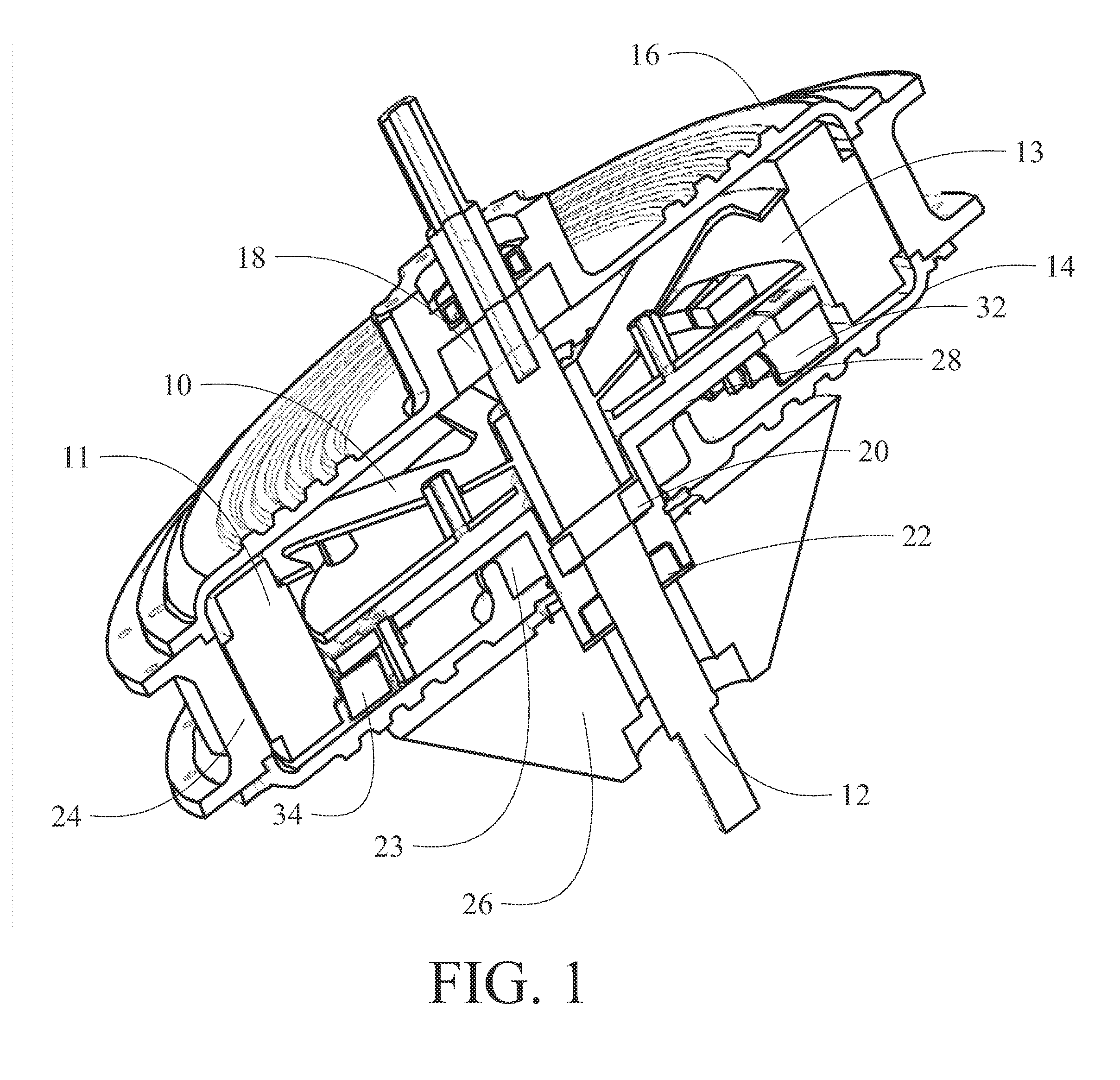
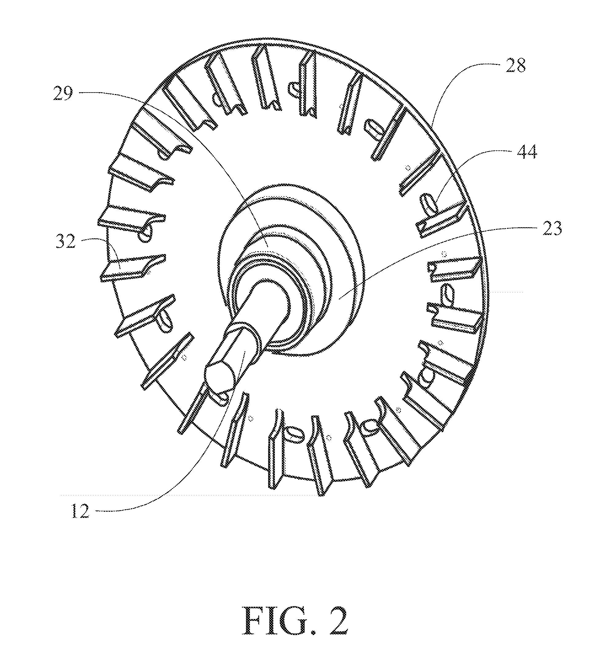
[0020]A section view of an embodiment incorporating the present invention is shown in FIG. 1. The integrated brushless direct current motor employs a stationary stator yoke 10 carrying stator windings 11 mounted to a non-rotating axle 12 carried within the rear wheel support frame of a bicycle. The stator yoke is an offset stamping providing a cylindrical cavity 13 around the axle. A split motor case having a gear side casting 14 and an outer side casting 16 encompasses the stator yoke and is rotationally carried by ...


PUM


Abstract

An integrated supplemental motor system for e-bikes incorporates a motor stator carried by a fixed axle with a torroidal cavity surrounding the axle. A motor rotor for interaction with the stator is supported by a motor casing rotatable on a plurality of bearings carried by the fixed axle. A torque member is concentrically carried within the torroidal cavity and has a first attachment engaged to a gear cluster for force input and a second resilient attachment for engagement to the motor casing. The torque member is urged by the gear cluster from a first no force position resiliently through a range of motion to a second maximum force position. A first element connected to the torque member has a set of first signal generation interfaces and a second element connected to the motor case has an equal set of second signal generation interfaces. The first and second signal generation interfaces are spaced in relation to the range of motion of the torque member. A sensor detects the consecutive first and second signal generation interfaces. A controller connected to the sensor receives a speed input and an effort input and provides a stator actuation current proportional to the spacing of the detected first and second signal generation interfaces.

Description

BACKGROUND INFORMATION[0001]1. Field[0002]Embodiments of the disclosure relate generally to the battery powered motors for bicycles and more particularly to embodiments for an integrated motor having an optical torque sensor and motor control electronics housed within a wheel hub case.[0003]2. Background[0004]Battery powered motors for providing propulsion assistance to a bicycle allow users to conveniently use bicycles for commuting as well as pleasure riding by reducing the physical effort required. The motor is controlled by a speed control loop using open or closed loop methods. Open loop methods rely on the user to respond to their pedal effort by manually adjusting the speed control lever. Closed loop systems will respond to pedal effort, but not control that effort, making it difficult to maintain a steady pedal effort under varying load conditions. Furthermore, most conventional motor controllers are more aggressive in their usage of battery energy because they are unable to...

Claims


Application Information

Patent Timeline
IPC IPC(8): G06F19/00H02K7/18F16H57/00B62M23/02
CPCB60L7/12Y10T74/19633B60L15/2045B60L2200/12B60L2220/44B60L2250/16B60L2270/36B62M6/45B62M6/65H02K1/187H02K7/14H02K11/0026H02K21/22Y02T10/641Y02T10/7005Y02T10/7283B60L11/007B60L11/1805H02K11/22Y02T10/72B60L50/20B60L50/52Y02T10/64Y02T10/70
Inventor RUBEN, MURRAY
Owner RUBEN MURRAY
Learn More