Catalytic burner apparatus for stirling engine

a technology of catalytic burner and stirling engine, which is applied in the direction of catalytic material combustion, furnaces, combustion types, etc., can solve the problems of insufficient heat distribution to the working gas, the solution offered by bohn is still too complex and inefficient for desired uses, and the problem of affecting the efficiency of the combustion engin

Active Publication Date: 2011-06-23
PRECISION COMBUSTION
View PDF30 Cites 23 Cited by
  • Summary
  • Abstract
  • Description
  • Claims
  • Application Information

AI Technical Summary

Benefits of technology

[0030](i) one or more outlet means for exhausting combustion gases from the chamber.

Problems solved by technology

Unfortunately, the solution offered by Bohn still is too complex and inefficient for desired uses.
Clark teaches that a problem still exists in the art with respect to the effective and efficient transfer of heat to a Stirling Engine heater head as late as 2003.
Another problem with burner devices for a Stirling Engine is described in U.S. Pat. No. 6,513,326 to Maceda, et al.
According to Maceda, heat is not uniformly distributed to the working gas within the heater tubes because a single burner device is used to generate and effectuate the heat transfer.
Unfortunately, the solution offered by Maceda still is too complex and inefficient for desired uses.

Method used


Image

  • Catalytic burner apparatus for stirling engine
  • Catalytic burner apparatus for stirling engine
  • Catalytic burner apparatus for stirling engine

Examples


Embodiment Construction

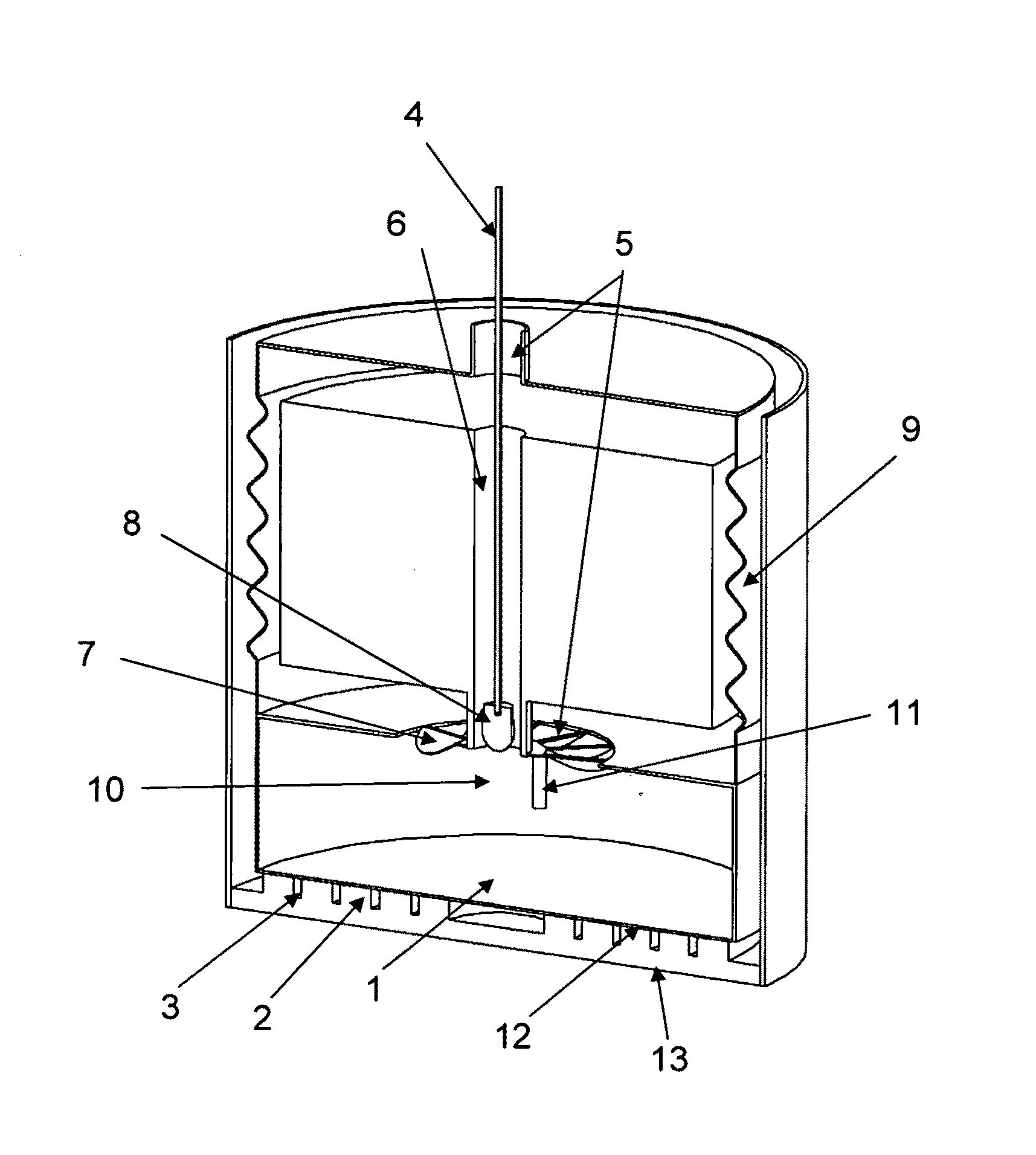
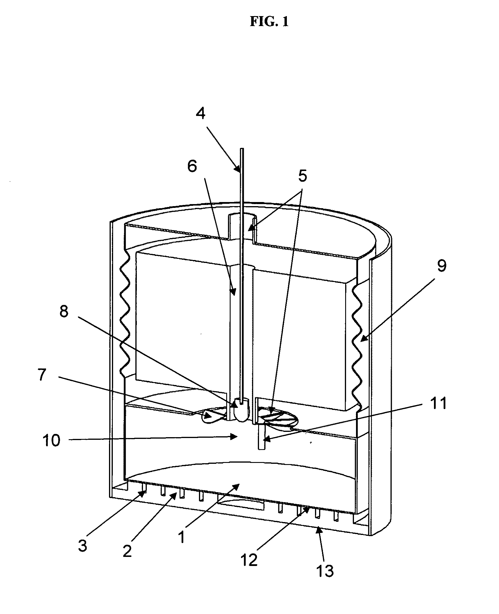
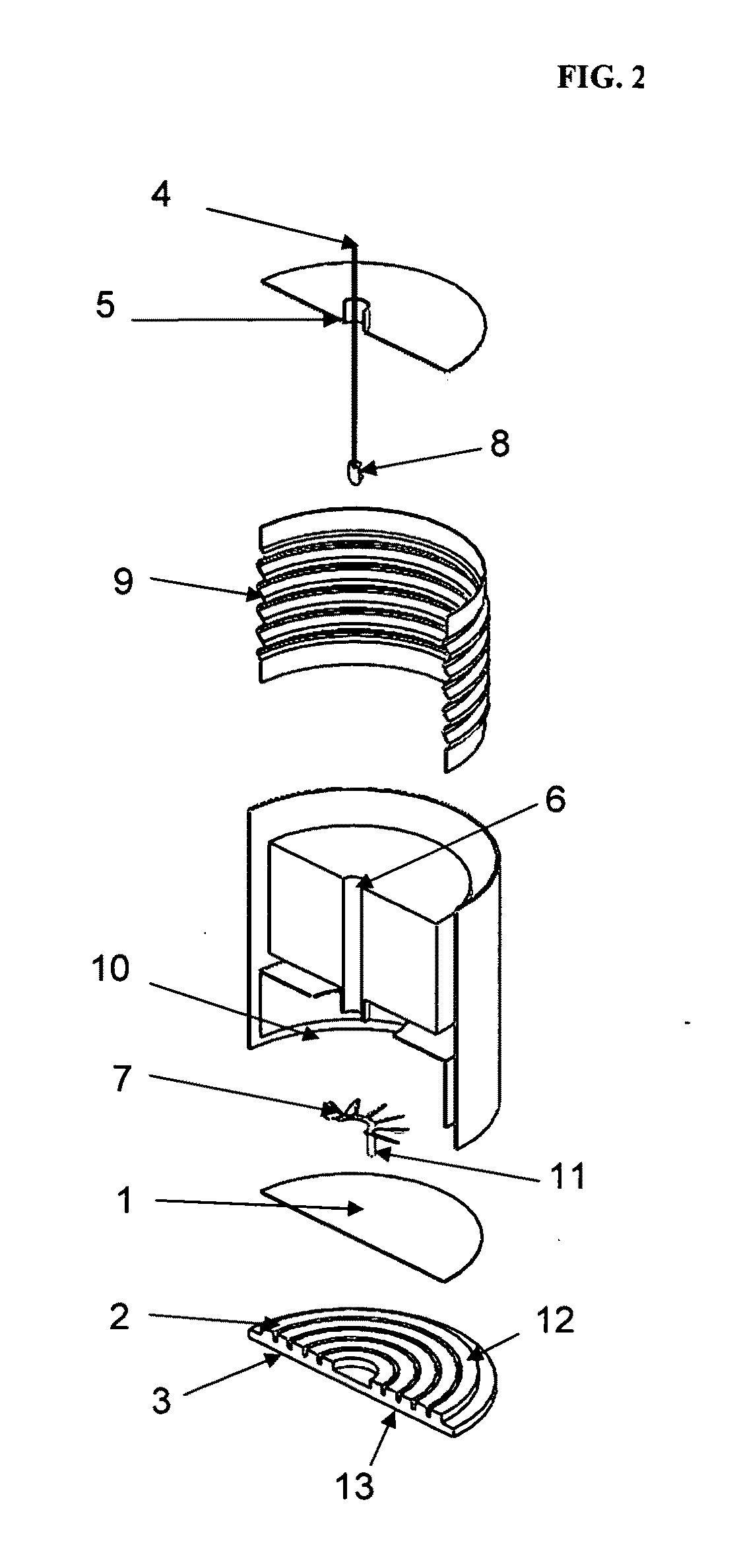
[0056]In one preferred embodiment of the invention, with reference to FIG. 1 (and exploded view in FIG. 2), fuel is introduced into a combustion chamber via fuel inlet 4; and oxidant is introduced into the combustion chamber via oxidant first inlet path 5. Optionally, additional oxidant may be introduced into the combustion chamber via oxidant second inlet path 6. The fuel and oxidant are mixed in combustion chamber 10. The mixing of fuel and oxidant are advantageously enhanced by incorporating a fuel nozzle atomizer 8 and swirler 7, described hereinafter. The mixture of fuel and oxidant contacts combustion catalyst 1 positioned within the chamber. The catalyst is lit-off using ignition means 11, and flameless catalytic combustion occurs with formation of combustion products and heat of reaction. Advantageously, combustion catalyst 1 comprises an ultra-short-channel-length metal substrate; preferably, an ultra-short-channel-length metal substrate in a mesh or foam form. More prefera...


PUM


Abstract

The invention provides an apparatus for generating heat and transferring the heat to a heater head of an external combustion engine, preferably, a Stirling engine. Fuel and air are introduced into a combustion chamber and mixed to form an air/fuel mixture. The air/fuel mixture is combusted over a combustion catalyst positioned in physical contact with a heat spreader, which itself is positioned in physical contact with a heat acceptor surface. The heat acceptor surface is secured in thermal communication with the heater head. Depending upon the design of the heater head, heat flux from the heat acceptor surface into the heater head may occur radially or non-radially.

Description

CROSS-REFERENCE[0001]This application is a continuation-in-part of U.S. patent application Ser. No. 11 / 803464, filed May 14, 2007, which claims the benefit of U.S. Provisional Application No. 60 / 799857, filed May 13, 2006. This application is a continuation of U.S. patent application Ser. No. 11 / 803464, filed May 14, 2007, which is also a continuation-in-part of U.S. patent application Ser. No. 11 / 364402, filed Feb. 28, 2006. The aforementioned priority applications are incorporated herein in their entirety by reference.GOVERNMENT RIGHTS[0002]This invention was made with government support under U.S. Contract No. N00014-08-C-0286. The U.S. government holds certain rights in this invention.FIELD OF THE INVENTION[0003]The present invention is directed to an apparatus for providing heat to an external combustion engine, particularly, towards providing heat to an internal heat acceptor, commonly referred to as a “heater head,” of an external combustion engine, more particularly, a Stirl...

Claims


Application Information

Patent Timeline
Patent Type & Authority Applications(United States)
IPC IPC(8): F02G1/043F23C13/00
CPCF02G1/043F02G1/055F02G2254/10F02G2254/70F23D14/24F23C13/00F23C13/08F23D11/00F02G2255/20
Inventor ROYCHOUDHURY, SUBIRBAIRD, BENJAMIN D.MASTANDUNO, RICHARD T.CROWDER, BRUCEFAZZINO, PAUL
Owner PRECISION COMBUSTION
Why Eureka
Try Eureka