Angular velocity sensor and electronic apparatus

a technology of angular velocity sensor and electronic equipment, which is applied in the direction of acceleration measurement using interia force, turn-sensitive devices, instruments, etc., can solve the problems of difficult to achieve the downsizing of the sensor, increase the thickness of the sensor, and difficulty in achieving thinning, etc., to achieve the effect of stable mounting

Inactive Publication Date: 2011-06-23
SONY CORP
View PDF4 Cites 26 Cited by
  • Summary
  • Abstract
  • Description
  • Claims
  • Application Information

AI Technical Summary

Benefits of technology

[0012]In the angular velocity sensor, the output signal corresponding to the third angular velocity can be calculated by simple calculation using a trigonometric function based on a detection signal of the first angular velocity by the first vibration element and a detection signal of the second angular velocity by the second vibration element. The third direction may be a direction orthogonal to the first direction on a first plane to which the first direction and the second direction belong. With this structure, it is possible to reduce a mounting area for the vibration elements on the support substrate, which are necessary for detecting the angular velocities in the biaxial directions orthogonal to each other on the plane to which the first direction and the second direction belong, with the result that the downsizing of the angular velocity sensor can be achieved. Further, in a case where the plane is parallel to the thickness direction of the sensor, the thinning of the sensor can be achieved.
[0015]The support substrate may have a first surface parallel to the first direction, on which the first vibration element and the second vibration element are mounted. With this structure, the mounting with the first surface of the support substrate as a reference can be performed, with the result that the reliability on the mounting of the first vibration element can be improved.
[0016]The first surface may be on a second plane orthogonal to the first plane. With this structure, the dimension of the support substrate in the thickness direction can be reduced, as compared to a case where detection axes of the vibration elements are arranged in axial directions orthogonal to each other.
[0018]The third vibration element may be mounted on the first surface of the support substrate. With this structure, it is possible to achieve the thinning of an angular velocity sensor in which first, second, and third vibration elements are mounted on a common substrate.
[0019]In the above structure, the support substrate may include a fixation portion in the first surface, the fixation portion positioning the second vibration element on a detection axis along the second direction. With this structure, it is possible to stably mount the second vibration element on the first surface.
[0025]As described above, according to the embodiments of the present invention, it is possible to achieve the thinning or downsizing of an angular velocity sensor.

Problems solved by technology

For that reason, a mounting area for those vibrators is made larger, which make it difficult to achieve the downsizing of the sensor.
Therefore, there arises a problem that the thickness dimension of the sensor is increased, and the thinning thereof is difficult to be achieved.

Method used


Image

  • Angular velocity sensor and electronic apparatus
  • Angular velocity sensor and electronic apparatus
  • Angular velocity sensor and electronic apparatus

Examples


first embodiment

Overall Structure

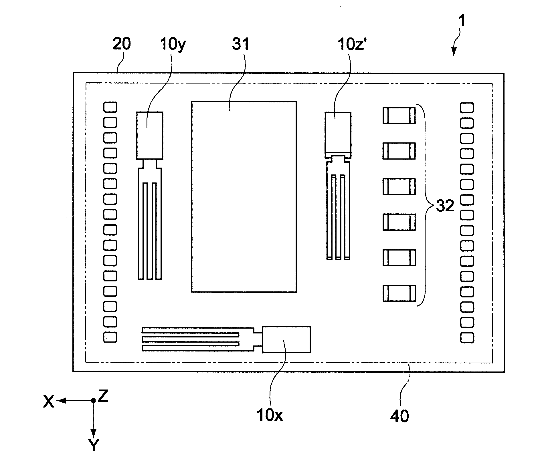
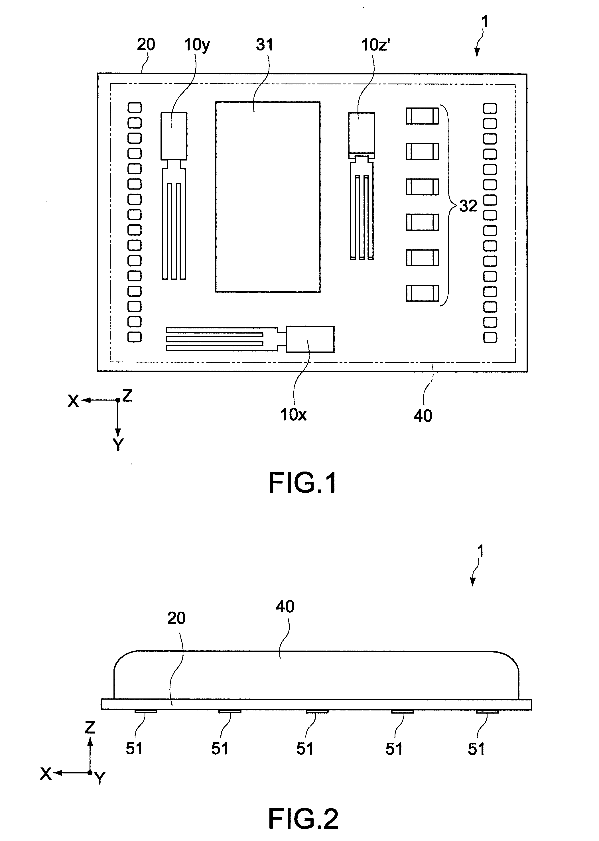
[0048]FIG. 1 is a schematic plan view showing an angular velocity sensor according to a first embodiment of the present invention. FIG. 2 is a side view of the angular velocity sensor provided with a cap. As shown in FIG. 1, assuming that three axes orthogonal to one another are an X axis, a Y axis, and a Z axis, an angular velocity sensor 1 of this embodiment has a horizontal direction in the X-axis direction, a vertical direction in the Y-axis direction, and a thickness direction in the Z-axis direction (front-rear direction of plane of FIG. 1).

[0049]The angular velocity sensor 1 includes three vibration elements 10x, 10y, and 10z′ and a support substrate 20. The vibration element 10x detects a rotating angular velocity about an axis parallel to the X axis, and the vibration element 10y detects a rotating angular velocity about an axis parallel to the Y axis. The vibration element 10z′ detects a rotating angular velocity about an axis parallel to a direction obliq...

second embodiment

[0097]FIG. 10 is a schematic plan view showing an angular velocity sensor according to a second embodiment of the present invention, and FIG. 11 is a side view showing a main portion thereof. In FIGS. 10 and 11, portions corresponding to those of the first embodiment are denoted by the same reference symbols, and detailed description thereof will be omitted.

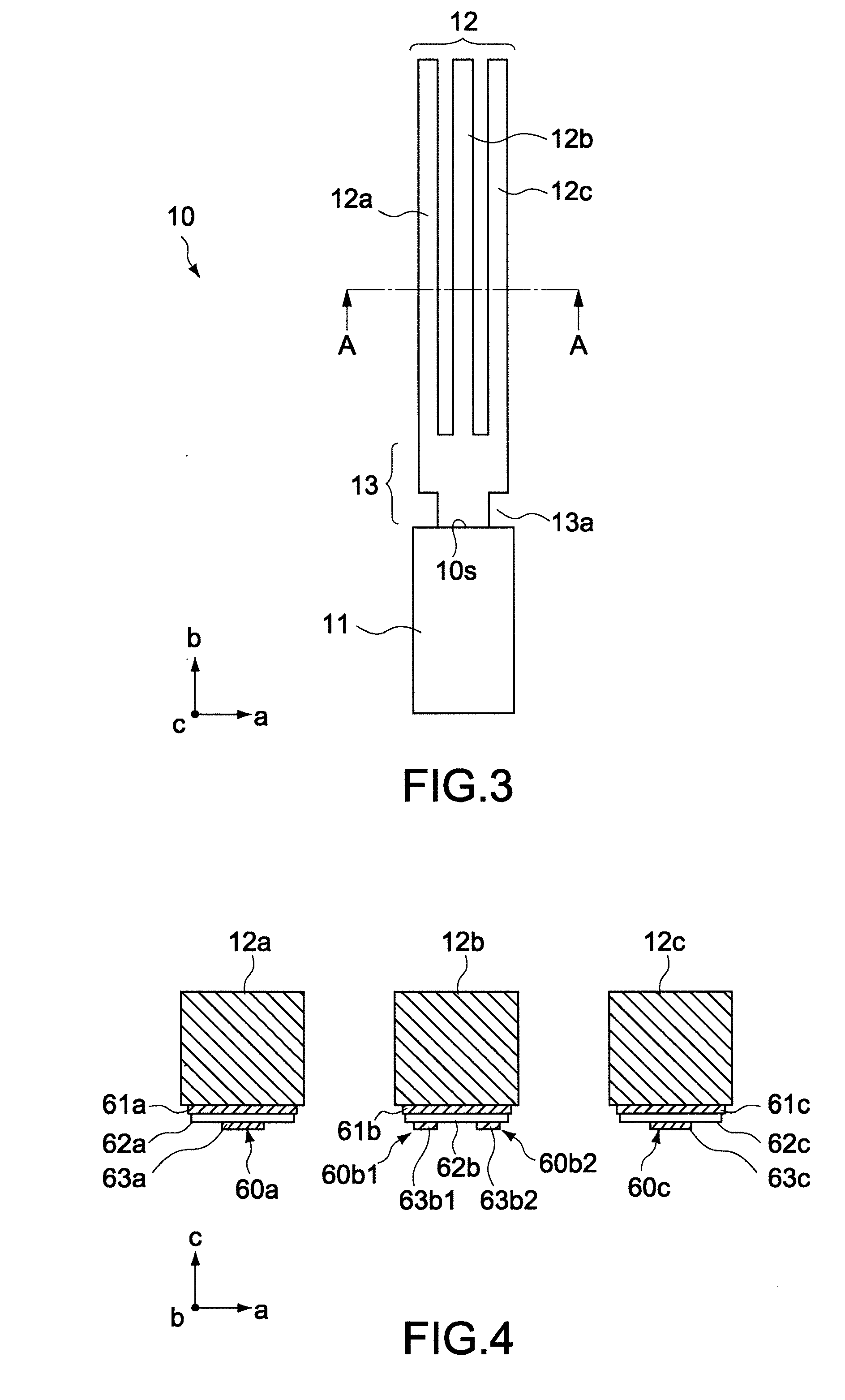
[0098]In an angular velocity sensor 2 of this embodiment, a vibration element 10z′ that detects an angular velocity about an axis parallel to a Z′ axis is mounted on a support substrate 20 such that an arrangement direction of vibration beams 12a to 12c thereof belongs to a plane perpendicular to the surface of the support substrate 20. A mounting surface 11m is formed on a base 11 of the vibration element 10z′ such that an extension direction of the vibration beams 12a to 12c in the state mounted on the support substrate 20 is aligned with an axial direction parallel to the Z′ axis.

[0099]The mounting surface 11m is formed on one...

third embodiment

[0101]FIG. 12 is a schematic plan view showing an angular velocity sensor according to a third embodiment of the present invention. In FIG. 12, portions corresponding to those of the first embodiment are denoted by the same reference symbols, and detailed description thereof will be omitted.

[0102]In an angular velocity sensor 3 of this embodiment, as in the second embodiment described above, a vibration element 10z′ is mounted on a support substrate 20 such that an arrangement direction of vibration beams 12a to 12c thereof belongs to a plane perpendicular to the surface of the support substrate 20. The angular velocity sensor 3 of this embodiment is different from that of the second embodiment described above in the structure in which the vibration element 10z′ is fixed to the support substrate 20, and has an auxiliary board 70 that connects the vibration element 10z′ and the support substrate 20. The auxiliary board 70 supports the vibration element 10z′ such that an extension dir...


PUM


Abstract

Provided is an angular velocity sensor including a first vibration element, a second vibration element, and a support substrate. The first vibration element detects a first angular velocity about an axis parallel to a first direction. The second vibration element detects a second angular velocity about an axis parallel to a second direction obliquely intersecting with the first direction, and generates an output signal corresponding to a third angular velocity about an axis parallel to a third direction orthogonal to the first direction. The support substrate supports the first vibration element and the second vibration element.

Description

BACKGROUND OF THE INVENTION[0001]1. Field of the Invention[0002]The present invention relates to an angular velocity sensor and an electronic apparatus that are used for detecting camera shake in a video camera, movements in a virtual reality apparatus, and directions in a car navigation system, for example.[0003]2. Description of the Related Art[0004]As angular velocity sensors for consumer use, vibratory gyroscopes are widely used. A vibratory gyroscope detects an angular velocity by vibrating a vibrator at a predetermined frequency and detecting Coriolis force generated in the vibrator with use of a piezoelectric element or the like. The gyroscope above is incorporated in electronic apparatuses such as a video camera, a virtual reality apparatus, and a car navigation system, each of which is used as a sensor for detecting camera shake, movements, directions, or the like.[0005]In a case where this type of gyroscope is used for detecting a change in posture in a space, there is kno...

Claims


Application Information

Patent Timeline
Patent Type & Authority Applications(United States)
IPC IPC(8): G01C19/56G01C19/5628
CPCG01C19/5628
Inventor INAGUMA, TERUOHONDA, JUNICHIAOTO, TAKANORIHINO, KOKITAKAHASHI, KAZUOONUMA, HIROSHI
Owner SONY CORP
Why Eureka
Try Eureka