Inertial sensor and method of manufacturing the same

a technology ofinertial sensor and manufacturing method, which is applied in the direction of turning-sensitive devices, acceleration measurement using interia force, instruments, etc., can solve the problems ofinertial sensor size reduction and performance increase, which have not yet been developed, and achieve high-performance sensitivity

Inactive Publication Date: 2011-06-23
SAMSUNG ELECTRO MECHANICS CO LTD
View PDF10 Cites 31 Cited by
  • Summary
  • Abstract
  • Description
  • Claims
  • Application Information

AI Technical Summary

Benefits of technology

[0009]Accordingly, the present invention has been made keeping in mind the problems encountered in the related art and the present invention is intended to provide an inertial sensor which includes a mass element formed such that the distal portion thereof has a larger width than the width of the proximal portion in contact with a diaphragm, so that a spring constant is decreased and the distance from the center of the diaphragm to the center of the mass element is increased, thus achieving high performance sensitivity, and also to provide a method of manufacturing the same.

Problems solved by technology

However, an inertial sensor which is reduced in size and increased in performance at the same time has not yet been developed.

Method used


Image

  • Inertial sensor and method of manufacturing the same
  • Inertial sensor and method of manufacturing the same
  • Inertial sensor and method of manufacturing the same

Examples


fourth embodiment

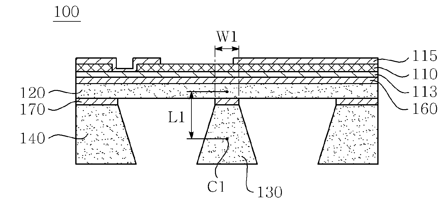
[0037]When comparing the center C1 of gravity of the mass element 130 according to the present embodiment with the center C4 of gravity of the mass element 130 the distance from the center of gravity to the diaphragm 120 can be seen to increase (L4→L1). Thus, the moment is increased, and the angular displacement is increased, ultimately raising the output of torsional mode.

[0038]Also, the width W1 of the proximal end of the mass element 130 according to the present embodiment is narrower than the width W4 of the proximal end of the mass element 130 according to the fourth embodiment. Thus, as the width of the diaphragm 120 integrated with the mass element 130 is also decreased, the actual length of the diaphragm 120 which is responsible for the functioning thereof becomes lengthened. Thereby, the spring constant of the diaphragm 120 is decreased and the linear displacement is increased, ultimately increasing the output of translation mode.

[0039]Though the process of manufacturing t...

second embodiment

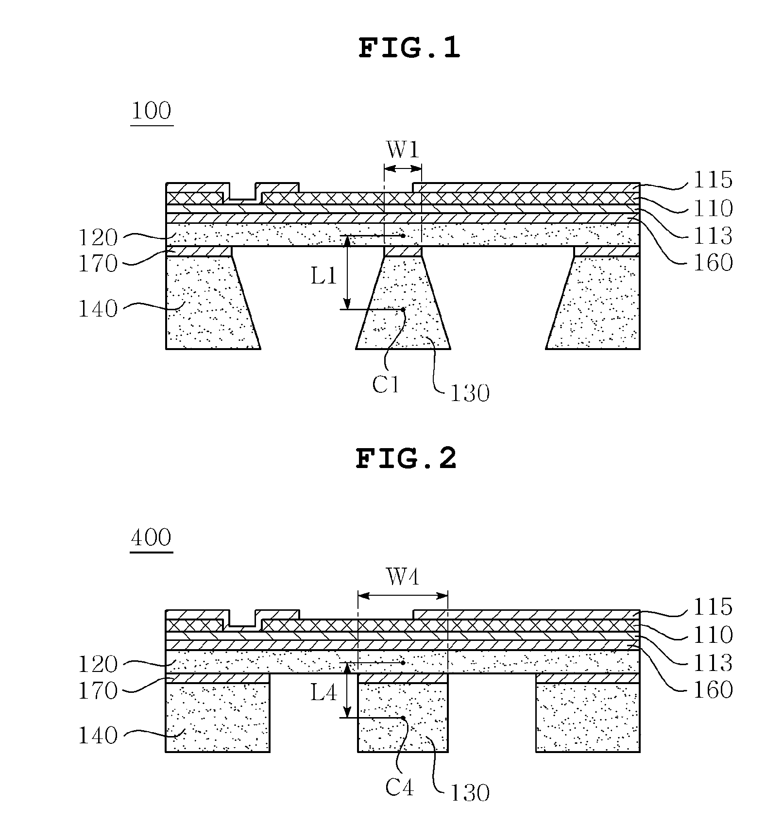
[0041]FIG. 3 is a cross-sectional view showing an inertial sensor according to the present invention.

[0042]As shown in FIG. 3, the inertial sensor 200 according to the present embodiment is apparently different in terms of the shape of a mass element 130 from the inertial sensor 100 according to the first embodiment. Thus, in the present embodiment, the shape of the mass element 130 will be mainly described, and the description which overlaps with that of the first embodiment will be omitted.

[0043]The mass element 130 according to the present embodiment includes a connector 133 in contact with the diaphragm 120 and a main body 135 having a predetermined width larger than the width of the connector 133 and extending so as to be stepped from the connector 133. Because the connector 133 having a width narrower than that of the main body 135 is provided, when comparing the center C2 of gravity of the mass element 130 according to the present embodiment with the center C4 of gravity of t...

third embodiment

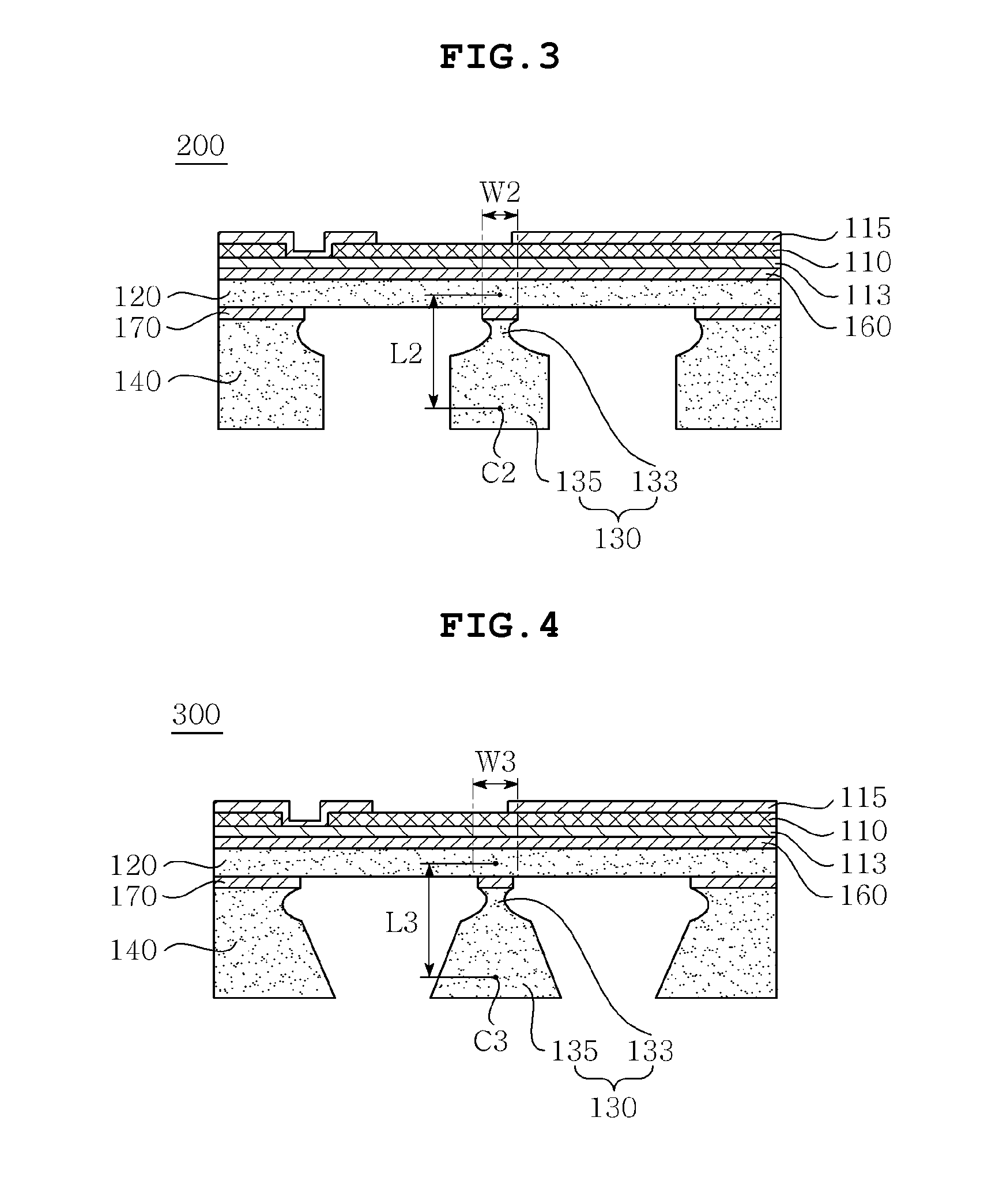
[0045]FIG. 4 is a cross-sectional view showing an inertial sensor according to the present invention.

[0046]As shown in FIG. 4, the inertial sensor 300 according to the present embodiment is quite different in terms of the shape of the mass element 130 from the inertial sensors 100, 200 according to the first and second embodiments. In particular, the shape of the mass element 130 according to the present embodiment includes a combination of the shape of the mass element 130 according to the first embodiment and the shape of the mass element 130 according to the second embodiment. What is mainly described below is the shape of the mass element 130.

[0047]The mass element 130 according to the present embodiment includes a connector 133 in contact with the diaphragm 120 and a main body 135 having a predetermined width larger than the width of the connector 133 and extending so as to be stepped from the connector 133, in which the predetermined width of the main body 135 increases from a...


PUM

PropertyMeasurementUnit
widthaaaaaaaaaa
massaaaaaaaaaa
anisotropicaaaaaaaaaa

Abstract

Disclosed herein is an inertial sensor, which includes a diaphragm having a piezoelectric element or a piezoresistive element formed on one surface thereof, a mass element integrated with the center of the other surface of the diaphragm in which the distal end of the mass element has a larger width than the width of the proximal end in contact with the diaphragm, and a supporter formed along the edge of the other surface of the diaphragm, so that the use of the mass element having the above shape results in decreased spring constant and increased distance from the center of the diaphragm to the center of the mass element, thereby simultaneously realizing a reduction in the size of the inertial sensor and an increase in performance thereof. A method of manufacturing the inertial sensor is also provided.

Description

CROSS REFERENCE TO RELATED APPLICATION[0001]This application claims the benefit of Korean Patent Application No. 10-2009-0129076, filed Dec. 22, 2009, entitled “Inertial sensor and producing method thereof”, which is hereby incorporated by reference in its entirety into this application.BACKGROUND OF THE INVENTION[0002]1. Technical Field[0003]The present invention relates to an inertial sensor and a method of manufacturing the same.[0004]2. Description of the Related Art[0005]Recently, an inertial sensor is being used not only for artificial satellites and munitions including missiles, pilotless airplanes and so on but also for vehicles including air bags, electronic stability control (ESC) systems, black boxes and so on, anti-shake camcorders, motion sensing mobile phones or game machines, and navigation systems.[0006]Inertial sensors are divided into acceleration sensors for measuring linear motion and angular velocity sensors for measuring rotational motion. The acceleration may ...

Claims


Application Information

Patent Timeline
Patent Type & Authority Applications(United States)
IPC IPC(8): G01P15/09H01L41/22G01P15/18
CPCG01C25/005G01P15/0922G01P15/18Y10T29/42H01L41/1138G01C19/56H01L41/1132G01P2015/084H10N30/308H10N30/302H01L21/00
Inventor JEUNG, WON KYUKIM, JONG WOON
Owner SAMSUNG ELECTRO MECHANICS CO LTD
Why Eureka
Try Eureka