Method for cutting with gas and apparatus for cutting with gas

a gas cutting and gas technology, applied in lighting and heating apparatus, combustion control, combustion types, etc., can solve the problem of cost drawback of gas cutting method, and achieve the effect of reducing the amount of hydrogen gas used and maintaining heat energy

Inactive Publication Date: 2011-06-23
NIPPON SANSO CORP
View PDF3 Cites 3 Cited by
  • Summary
  • Abstract
  • Description
  • Claims
  • Application Information

AI Technical Summary

Benefits of technology

According to the method for cutting with gas and the apparatus for cutting with gas of the present invention, it is possible to form a preheating flame preferably in each of heating and cutting the workpiece while maintaining heat energy needed, and decrease an amount of hydrogen gas used.
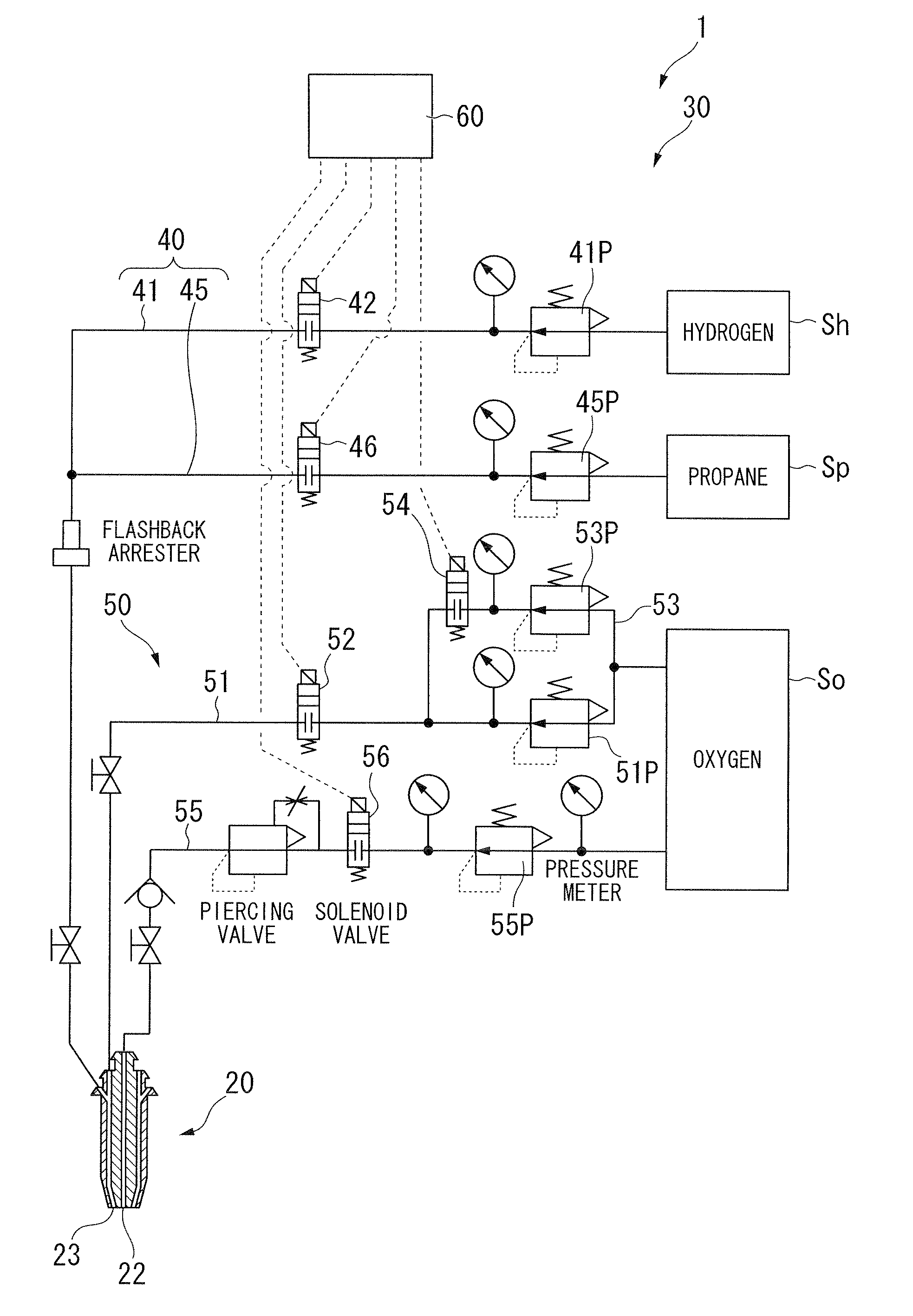
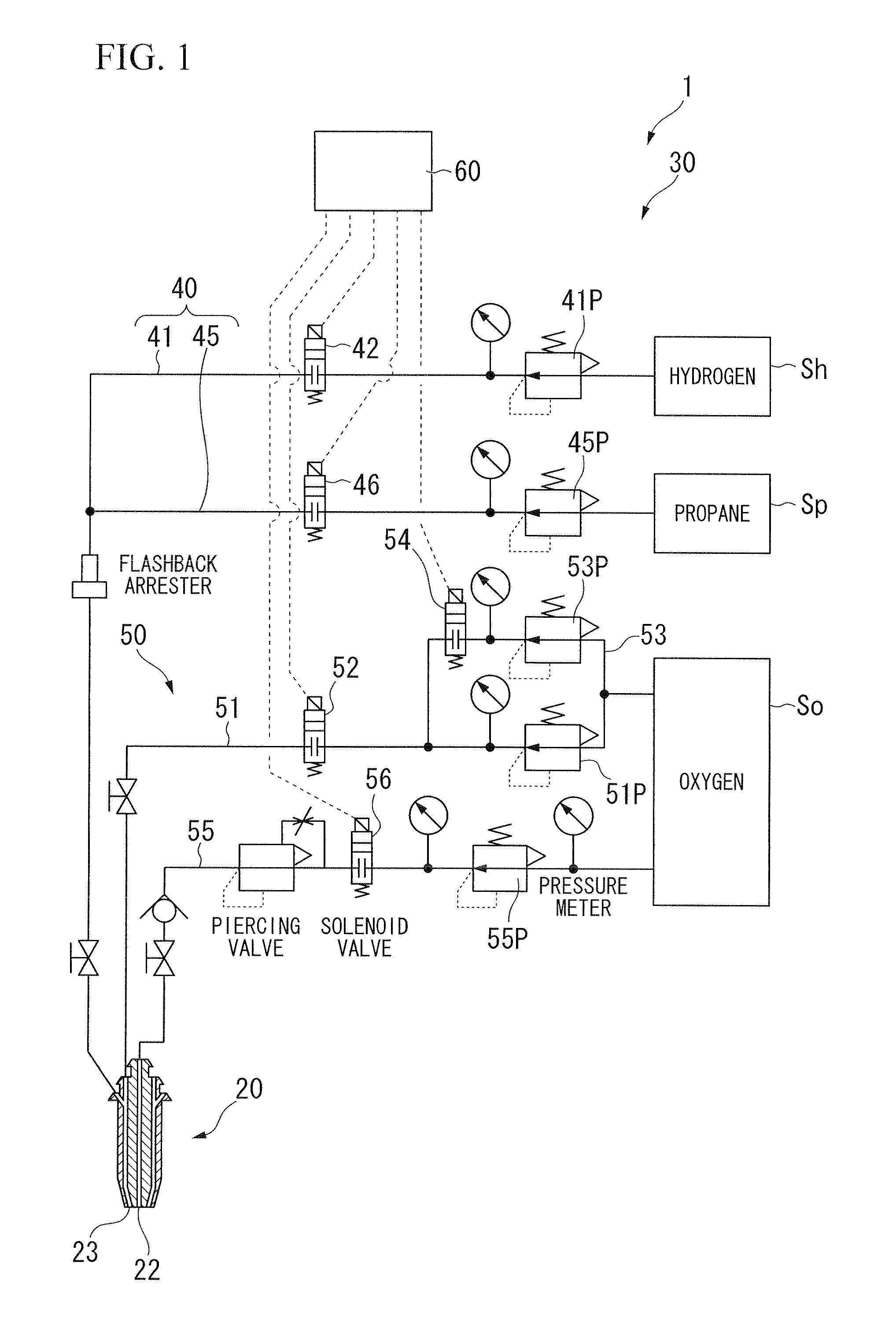
FIG. 1 is a schematic view showing a gas cutting device according to a first embodiment of the present invention.
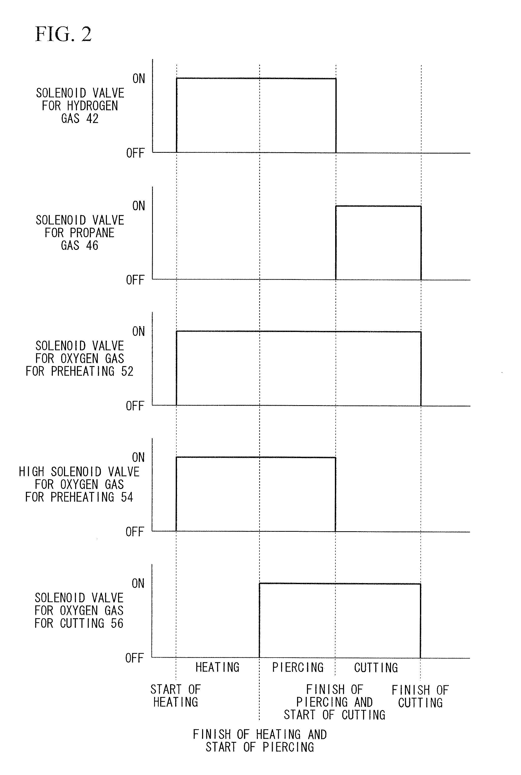
FIG. 2 is a time chart for explaining functions of the gas cutting device according to a first embodiment of the present invention.
FIG. 3 is a schematic view showing a gas cutting device according to a second embodiment of the present invention.
FIG. 4 is a time chart for explaining functions of the gas cutting device according to a second embodiment of the present invention.
FIG. 5 is a figure for explaining effects obtained by the method for cutting with gas according to the present invention.

Problems solved by technology

That is, this gas cutting method has a drawback of cost.

Method used


Image

  • Method for cutting with gas and apparatus for cutting with gas
  • Method for cutting with gas and apparatus for cutting with gas
  • Method for cutting with gas and apparatus for cutting with gas

Examples


first embodiment

the present invention is explained referring to FIGS. 1 and 2.

FIG. 1 shows a gas cutting system 1 according to the first embodiment. Reference numeral 20 shows a cutting tip, and 30 shows a gas cutting device. The gas cutting device 30 supplies oxygen gas and fuel gas into the cutting tip 20.

The cutting tip 20, which is pole shape, includes an oxygen gas hole for cutting 22 which is formed at the center of an end surface of the cutting tip 20, and a preheating hole 23 which is formed so as to surround the oxygen gas hole for cutting 22. To the preheating hole 23, fuel gas and oxygen gas are supplied from the gas cutting device 30. Oxygen gas is supplied from the gas cutting device 30 to the oxygen gas hole for cutting 22.

A workpiece is heated by a preheating flame, and cut (including piercing) by injecting oxygen gas from the oxygen gas hole for cutting 22 to the heated portion of the workpiece.

Moreover, the structure of the preheating hole and the cutting oxygen gas hole in the cut...

second embodiment

Next, the present invention is explained referring to FIGS. 3 and 4.

FIG. 3 is a schematic view showing a second gas cutting system. In FIG. 3, reference numeral 70 denotes a gas cutting device.

The gas cutting device 70 is different from the gas cutting device 30 in the following points. Specifically, hydrogen gas and propane gas are supplied by the solenoid valve for hydrogen gas 42 and the solenoid valve for propane gas 46 in the gas cutting device 30. In contrast, the supply of hydrogen gas and propane gas is controlled without steps by a mass-flow controller provided in the supply circuit for hydrogen gas 81 and the supply circuit for propane gas 85, which are disposed in the supply circuit for fuel gas 80, in the gas cutting device 70. The other components are the same as those in the gas cutting device 30. Therefore, an explanation of the same components is omitted in this embodiment.

The gas cutting device 70 includes a supply circuit for fuel gas 80, a supply circuit for oxyge...


PUM

PropertyMeasurementUnit
volumeaaaaaaaaaa
flow rateaaaaaaaaaa
temperatureaaaaaaaaaa

Abstract

The object of the present invention is to provide a method for cutting with gas which uses a cutting tip including a preheating hole for forming a preheating flame with a fuel gas and an oxygen gas for preheating, and an oxygen gas hole for cutting a workpiece by injecting oxygen gas for cutting, and which can decrease an amount of hydrogen gas used by supply a fuel gas to the preheating hole, which is appropriate in both heating and cutting the workpiece, and an apparatus for cutting with gas, and the present invention provides an apparatus for cutting with gas (30) which supplies an oxygen gas, and a fuel gas to a cutting tip (20) including a preheating hole (23) and an oxygen gas hole for cutting (22), wherein the apparatus (30) includes a supply circuit for oxygen gas (50), a supply circuit for hydrogen gas (41), a supply circuit for hydrocarbon-based gas (45), and a gas supply control means (60), and the gas supply control means (60) can alter a ratio of the hydrogen gas and the hydrocarbon-based gas which are supplied to the preheating hole in a case of heating the workpiece and a case of cutting the workpiece.

Description

TECHNICAL FIELDThe present invention relates to a method for cutting with gas which uses a cutting tip including a preheating hole for forming a preheating flame with a fuel gas and an oxygen gas for preheating, and an oxygen gas hole for cutting a workpiece by injecting oxygen gas for cutting, and an apparatus for cutting with gas.Priority is claimed on Japanese Patent Application, No. 2008-236703, filed on Sep. 16, 2008, the contents of which are incorporated herein by reference.BACKGROUND ARTFor example, when a workpiece, such as a steel plate is cut, a gas cutting method has been widely used in which a cutting start point in the workpiece is heated to a temperature at where an oxidation reaction can be carried out by a preheating flame generated at a preheating hole, and the workpiece is burned and melted to be cut by injecting oxygen gas with a high purity from a cutting oxygen gas hole toward the heated portion.In the gas cutting method, while the cutting start point in the wo...

Claims


Application Information

Patent Timeline
Patent Type & Authority Applications(United States)
IPC IPC(8): B23K7/00B23K7/06
CPCB23K7/008F23C2900/9901F23D14/32F23D14/42F23K5/007Y02E20/344F23K2900/05004F23N3/005F23N2037/08F23N2041/11F23K2401/201F23N2237/08F23N2241/11F23K2400/201
Inventor NAGAHORI, MASAYUKIKAMIKIHARA, HIROTAKATAKEDA, TAKASHISATO, TOYOYUKIYAMAMOTO, YASUYUKIKATO, TAKASHI
Owner NIPPON SANSO CORP
Why Eureka
Try Eureka