Method of constructing a fixed-wing aircraft

a technology for fixed-wing aircraft and wings, which is applied in the field of aircraft structure, can solve the problems of high number of parts needed for assembling the wings to the fuselage and the awkwardness of fastening operation, and achieve the effect of reducing the time and simplifying the assembly of the wings

Active Publication Date: 2011-06-23
AIRBUS OPERATIONS (SAS)
View PDF8 Cites 69 Cited by
  • Summary
  • Abstract
  • Description
  • Claims
  • Application Information

AI Technical Summary

Benefits of technology

[0005]An object of the invention is to simplify assembling the wings to the fuselage, in particular in order to reduce the time taken.

Problems solved by technology

Unfortunately, the number of parts needed for assembling the wings to the fuselage is relatively high.
This fastening operation is very awkward, given its duration and the number of parts to be assembled together.

Method used


Image

  • Method of constructing a fixed-wing aircraft
  • Method of constructing a fixed-wing aircraft
  • Method of constructing a fixed-wing aircraft

Examples


Embodiment Construction

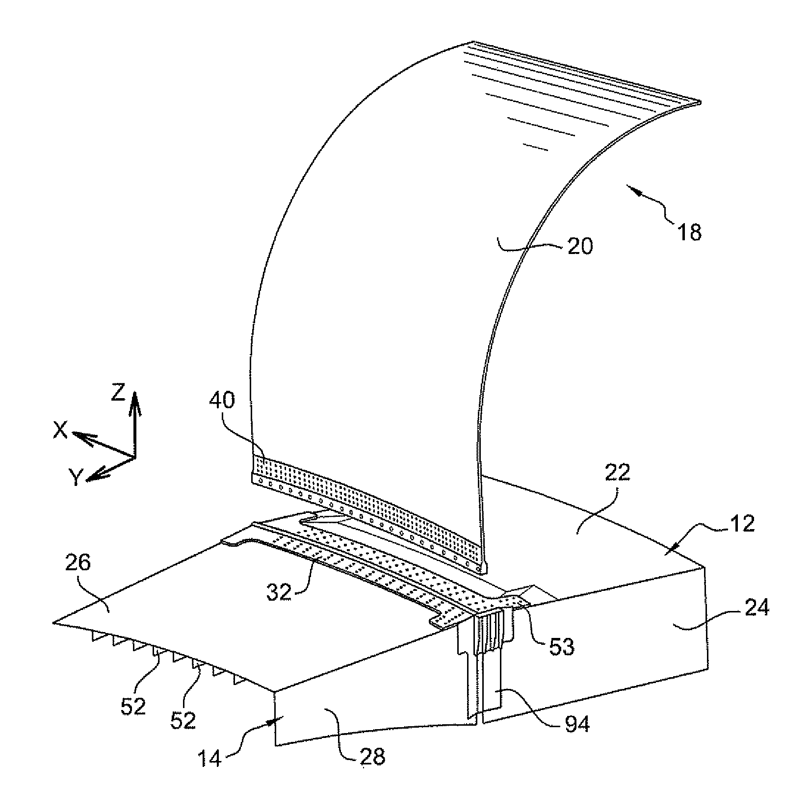
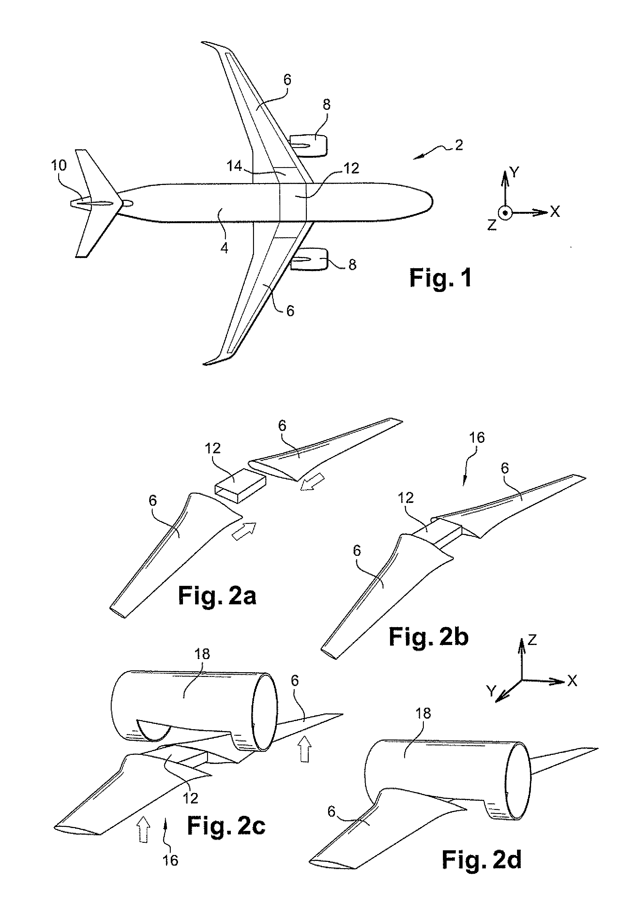
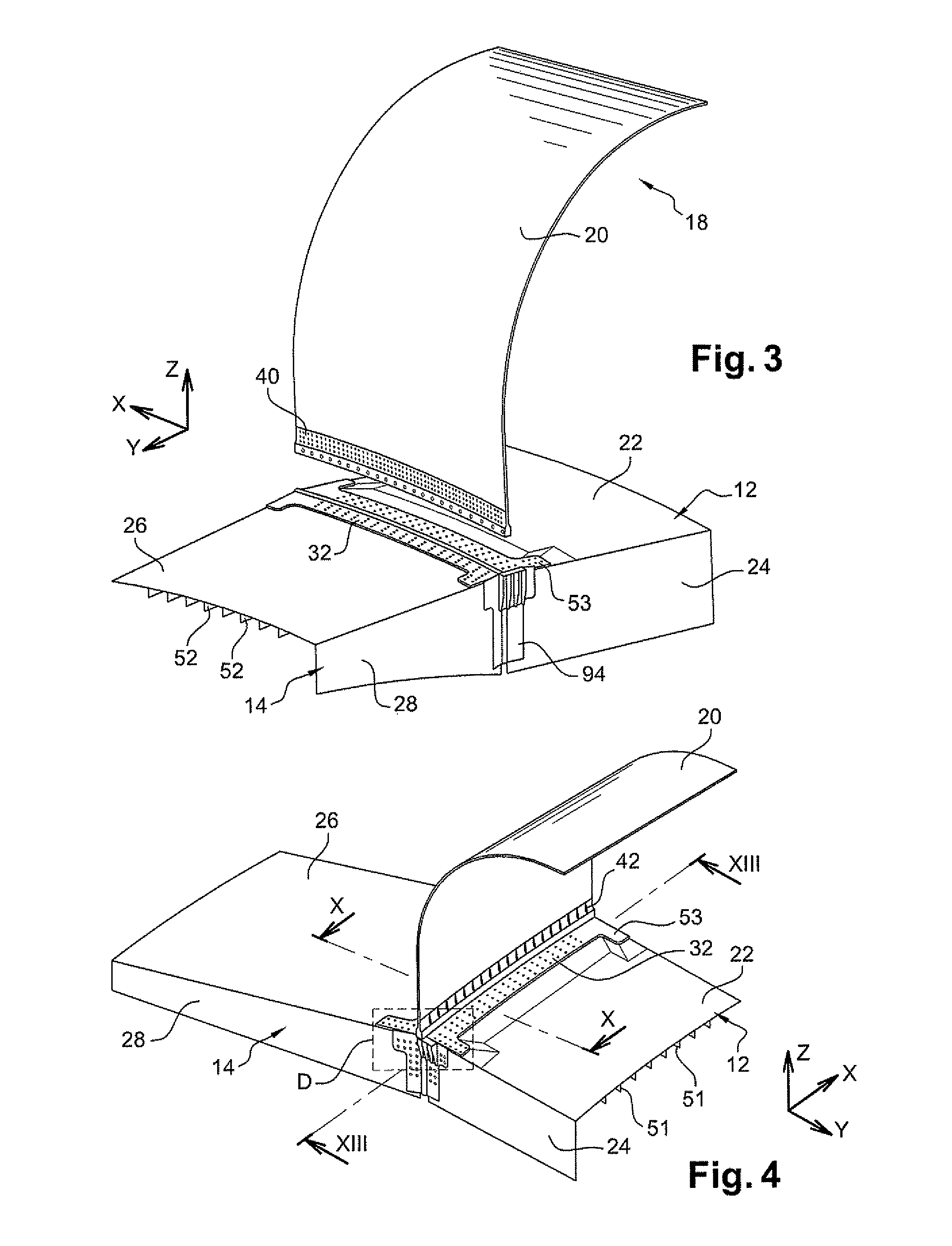
[0044]In the embodiment shown in FIG. 1, the aircraft of the invention is an aerodyne, and specifically an airplane 2. It comprises a fuselage 4, two wings 6, each carrying an engine 8, a tail 10, and a central wing box 12. The wing box is generally in the form of a rectangular parallelepiped. Each of the wings 6 includes at its proximal end adjacent to the fuselage a respective lateral wing box 14. The wings are fastened to the fuselage via the lateral boxes that are fastened to the central box 12. Below, the conventional X, Y, Z frame of reference is used in which the direction X is horizontal and parallel to the flying direction of the airplane, the direction Y is horizontal and perpendicular to the direction X, while the direction Z is vertical. Over the major fraction of its length, the fuselage is in the form of a tapering cylinder of generally circular cross-section with its axis parallel to the direction X.

[0045]The airplane shown is a commercial airliner. It is suitable for...


PUM

PropertyMeasurementUnit
distanceaaaaaaaaaa
distanceaaaaaaaaaa
diameteraaaaaaaaaa

Abstract

The following steps are performed in the method of constructing an aircraft: taking a subassembly comprising two wings that are rigidly fastened together, and fitting it to a fuselage wall; and fastening the subassembly to the wall by means of fastener elements that are distinct from the subassembly and that present main axes that are vertical.

Description

FIELD OF THE INVENTION[0001]The invention relates to the structure of aircraft, and in particular to the junction between the wing and the fuselage.BACKGROUND OF THE INVENTION[0002]Conventionally, an airplane comprises two wings that are connected to the fuselage via a central wing box. The function of the wing box is to take up forces coming from the wings and to transmit them to the fuselage.[0003]The building of the central segment of the fuselage thus begins by constructing the central wing box around which the skin elements and the frames constituting the fuselage are added. The box has horizontal top and bottom panels. Each wing has a lateral wing box via which it is fastened to the central box. These lateral boxes also present top and bottom panels. Each top panel of the wings is connected to the top panel of the central box by means of a part that is referred to as a cross or as being cruciform, given the characteristic shape of its section. The same part is also used for co...

Claims


Application Information

Patent Timeline
Patent Type & Authority Applications(United States)
IPC IPC(8): B64C1/26B23P11/00B64C3/00B64C1/00
CPCB64C1/26B64C2001/0072Y10T29/49947Y02T50/433B64F5/0009B64F5/10Y02T50/40
Inventor DELAHAYE, ROMAINGALLANT, GUILLAUME
Owner AIRBUS OPERATIONS (SAS)
Why Eureka
Try Eureka