Converter with crossover frequency responsive to switching frequency

a technology of crossover frequency and switching frequency, which is applied in the direction of power conversion system, dc-dc conversion, instruments, etc., can solve problems such as the change of crossover frequency

Active Publication Date: 2011-06-23
MICROSEMI
View PDF16 Cites 19 Cited by
  • Summary
  • Abstract
  • Description
  • Claims
  • Application Information

AI Technical Summary

Benefits of technology

[0012]Advantageously, a single terminal of the power converter thus controls the switching frequency, er...

Problems solved by technology

This is however disadvantageous, since in the event that the user has selected, by means of the external component value, a switching frequency in excess of the lowest switching frequency allowed, a higher crossover frequency which allows for a ...

Method used


Image

  • Converter with crossover frequency responsive to switching frequency
  • Converter with crossover frequency responsive to switching frequency
  • Converter with crossover frequency responsive to switching frequency

Examples


Embodiment Construction

[0033]Before explaining at least one embodiment of the invention in detail, it is to be understood that the invention is not limited in its application to the details of construction and the arrangement of the components set forth in the following description or illustrated in the drawings. The invention is applicable to other embodiments or of being practiced or carried out in various ways. Also, it is to be understood that the phraseology and terminology employed herein is for the purpose of description and should not be regarded as limiting.

[0034]The invention is herein described in relation to a buck converter, however this is not meant to be limiting in any way. The teaching of the invention is equally applicable to any power converter configuration having a feedback loop, including, without limitation, a boost converter and a flyback converter.

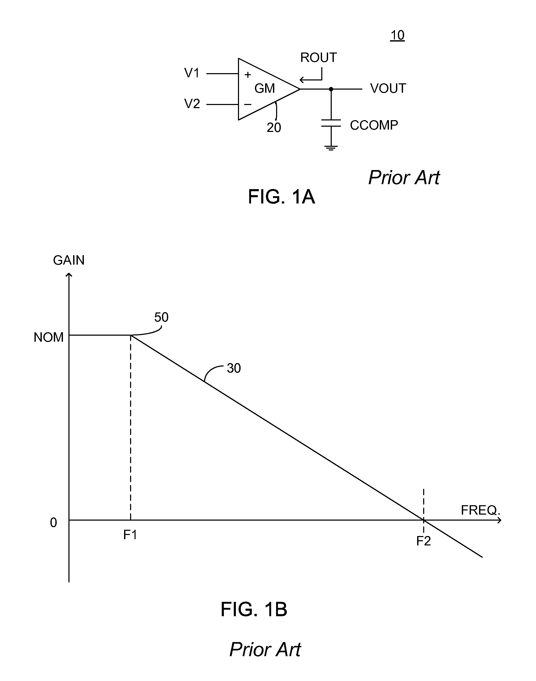
[0035]FIG. 1A illustrates a high level schematic diagram of a transconductance-C structure 10, in accordance with the prior art, compri...


PUM


Abstract

A power converter constituted of: a reference source; a clock generator exhibiting a variable frequency output, the value of the frequency of the variable frequency output responsive to an input signal; and an error amplifier in communication with the reference source, the error amplifier exhibiting a gain whose value is responsive to the input signal. Preferably the error amplifier is a transconductance amplifier. In one embodiment the power converter further exhibits a current squarer, arranged to produce a squared value of the input signal and provide the squared value to the transconductance amplifier.

Description

CROSS-REFERENCE TO RELATED APPLICATIONS[0001]This application claims priority from U.S. Provisional Patent Application Ser. No. 61 / 288,298 filed Dec. 20, 2009, the entire contents of which is incorporated herein by reference.TECHNICAL FIELD[0002]The present application relates to the field of DC / DC converters, and more particularly to a converter whose error amplifier crossover frequency is responsive to changes in the converter switching frequency.BACKGROUND OF THE INVENTION[0003]A DC / DC power converter receives an input direct current (DC) power, and converts it to a DC output power, typically exhibiting a different voltage than the input DC power. Control of the DC output power may be responsive to the output voltage or to the output current.[0004]A boost converter, also known as a step-up converter, is a power converter with an output DC voltage greater than its input DC voltage. It is a class of switching-mode power supply containing at least a first electronically controlled s...

Claims


Application Information

Patent Timeline
IPC IPC(8): G05F1/618
CPCH02M3/156
Inventor KWAN, KAIKIM, PETER
Owner MICROSEMI
Why Eureka
Try Eureka