Electromagnetic actuator having a magnetostrictive element and method for operating the electromagnetic actuator

a technology of electromagnetic actuator and magnetostrictive element, which is applied in the direction of magnetostrictive relay, electric motor with armature, magnetic body, etc., can solve the problems of unfavorable noise or hysteresis effect, difficult control of actuator, and still occur hysteresis effects impairing the controllability of the actuator, and achieve small hysteresis effect

Inactive Publication Date: 2011-06-23
ZF FRIEDRICHSHAFEN AG
View PDF5 Cites 2 Cited by
  • Summary
  • Abstract
  • Description
  • Claims
  • Application Information

AI Technical Summary

Benefits of technology

[0018]The signal preferably consists of a control signal for producing a control movement of the armature and an oscillating signal superimposed on the control signal for deforming the magnetostrictive element, the oscillating signal being in particular a chopper- or dither-signal. In this way the coil produces a fluctuating magnetic field, which on the one hand moves the armature to perform control tasks, and on the other hand also brings about a fluctuating deformation of the magnetostrictive element and hence an advantageous, continuous relative movement of the armature relative to its bearing arrangement.
[0019]Preferably, the frequency of the oscillating signal is high enough that by virtue of the oscillating signal, owing to its inertia and without excitation of the magnetostrictive element, the armature cannot move. This means that the frequency of the oscillating signal is preferably high enough that the armature of an actuator without a magnetostrictive element could not be moved by the oscillating signal alone, but would remain static owing to its inertia. Thanks to such high frequencies particularly small hysteresis effects are obtained, which could not be achieved without the magnetostrictive element. Thus, the magnetostrictive element used according to the invention eliminates the limits imposed in the prior art by the inertia of the armature.

Problems solved by technology

When the coil is energized, as a result of friction the movement sequence of the armature may be irregular and this can cause undesired noise or hysteresis effects.
In particular, the associated hysteresis effects make it more difficult to control the actuator.
In practice, however, hysteresis effects that impair the controllability of the actuator still occur.
However, this is only possible within certain limits since with increasing frequency the speed of the armature decreases again because of its inertia, and consequently, above a limit frequency the advantageous continuous armature movement ceases.

Method used


Image

  • Electromagnetic actuator having a magnetostrictive element and method for operating the electromagnetic actuator
  • Electromagnetic actuator having a magnetostrictive element and method for operating the electromagnetic actuator
  • Electromagnetic actuator having a magnetostrictive element and method for operating the electromagnetic actuator

Examples


Embodiment Construction

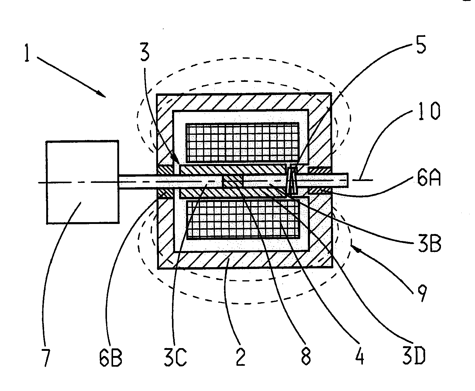
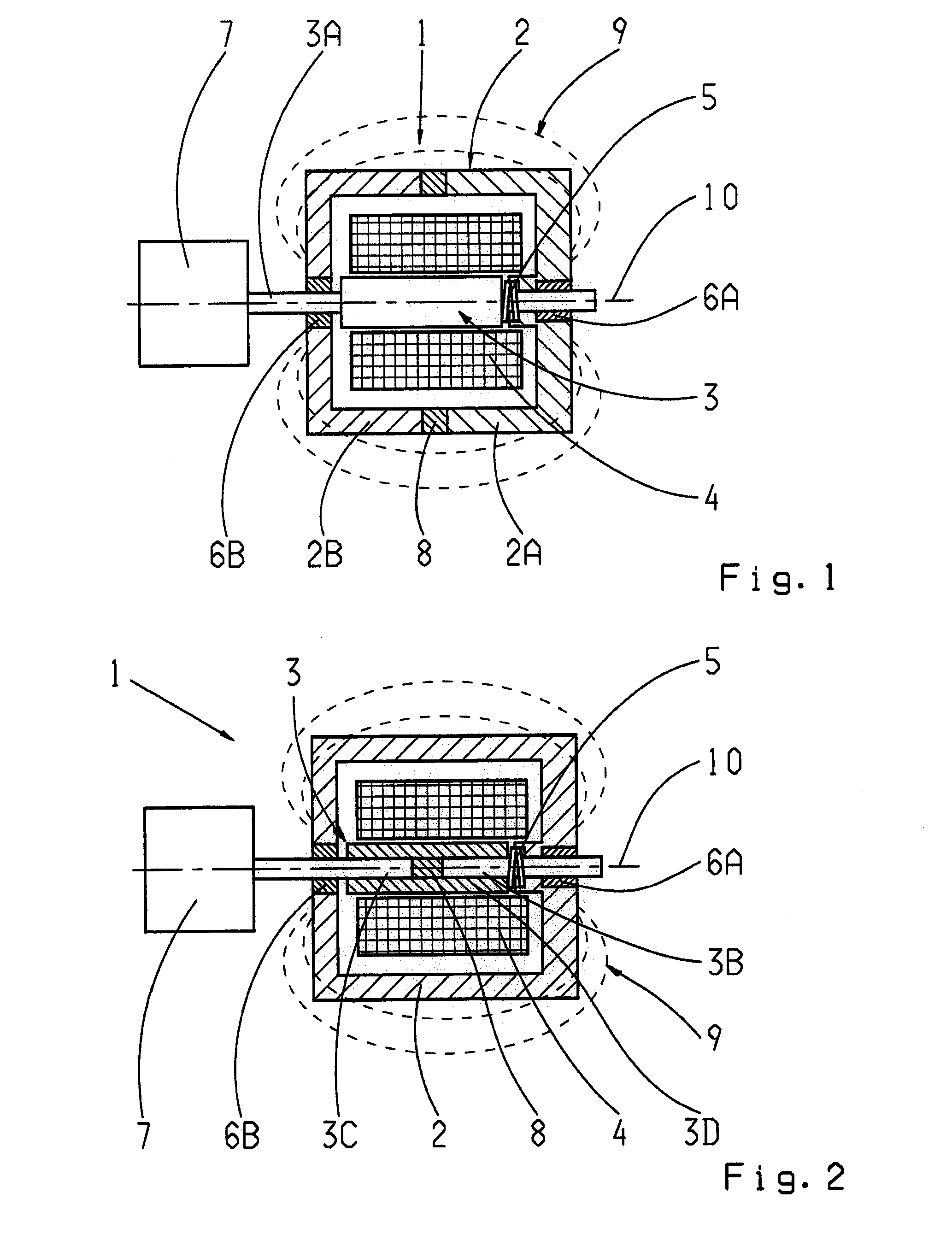
[0025]The actuator 1 shown in FIG. 1 has a housing 2 inside which are arranged an armature 3, a bearing arrangement 6A, 6B, at least one coil 4 and an elastic spring 5. In this case the bearing arrangement consists of two bearings 6A, 6B in the form of slide bearings, which guide an armature rod 3A of the armature that projects out of the housing 2. The armature rod 3A serves to actuate a device 7, for example a pneumatic or hydraulic pressure control valve of a vehicle transmission.

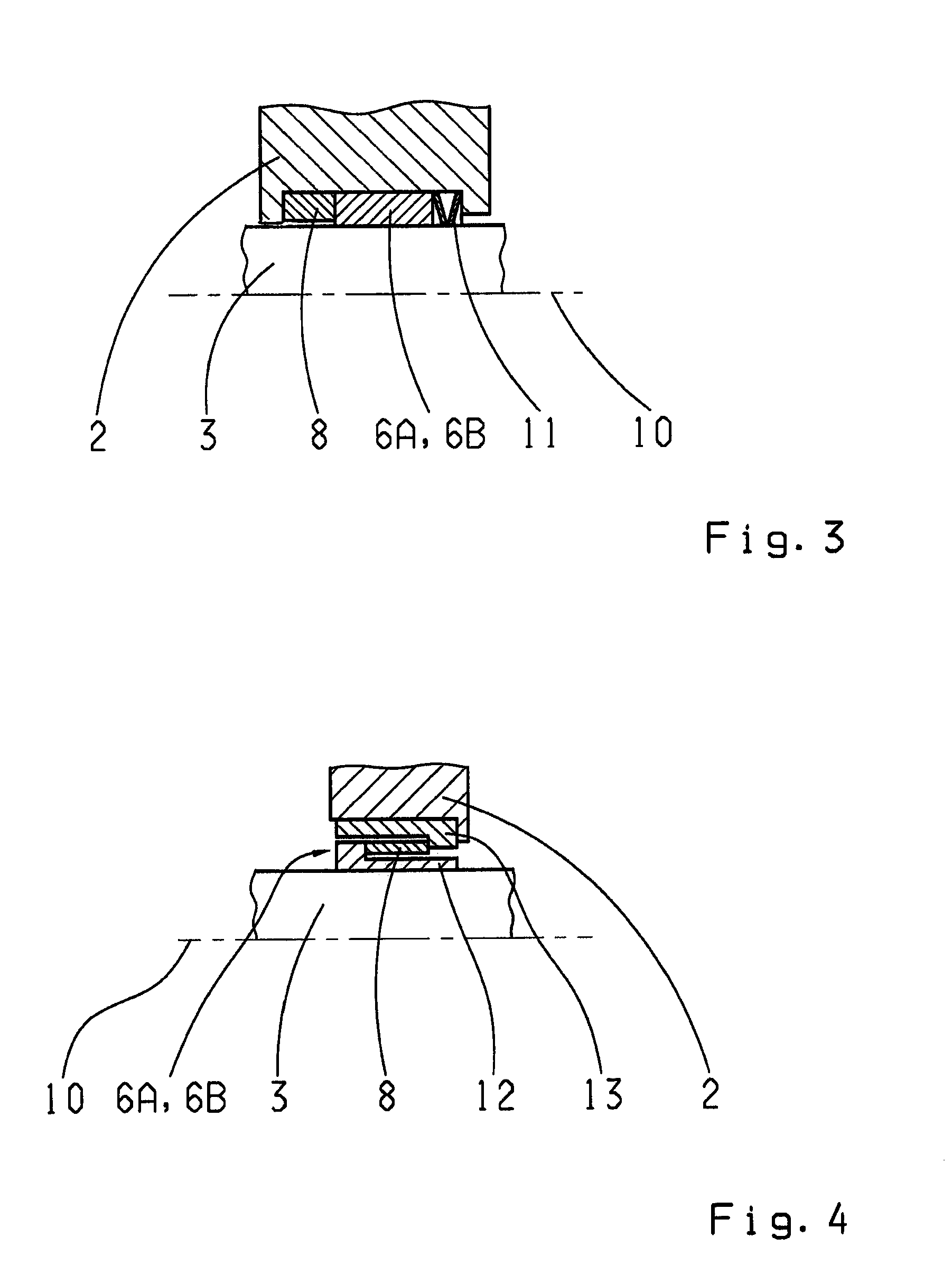
[0026]The housing 2 is divided in two portions, the first housing portion 2A firmly holding the first bearing 6A of the bearing arrangement and the second housing portion 2B firmly holding the second bearing 6B. Between the two housing portions 2A, 2B is arranged a magnetostrictive element 8 which connects the two housing portions 2A, 2B.

[0027]When the coil 4 is energized with a signal, then depending on the design of the coil 4 and the armature 3, the armature 3 can be moved either in rotation or in tra...


PUM

PropertyMeasurementUnit
magnetostrictiveaaaaaaaaaa
magnetic fieldaaaaaaaaaa
frequencyaaaaaaaaaa

Abstract

An electromagnetic actuator (1) with an armature (3) mounted so that the armature can be moved by virtue of a bearing arrangement (6A, 6B) and an electric coil (4) is provided for moving the armature (3). A magnetostrictive element (8) is provided, by which relative movement between the armature (3) and at least part of the bearing arrangement (6A, 6B) is produced.

Description

[0001]This application claims priority from German patent application serial no. 10 2009 054 952.8 filed Dec. 18, 2009.FIELD OF THE INVENTION[0002]The invention relates to an electromagnetic actuator having an armature mounted to move by virtue of a bearing device and with a coil for moving the armature, and to a method for actuating the electromagnetic actuator.BACKGROUND OF THE INVENTION[0003]Such actuators are very commonly used for producing control movements, for example in valve devices of vehicles or in closing mechanisms of vehicle windows or doors. Depending on its intended purpose the armature can be moved by the coil either in rotation or in translation. To do this the coil is energized with a signal so that it produces a magnetic field, which in turn drives the armature that generates the control movement. The bearing device is designed in accordance with the desired movement direction of the armature and can therefore comprise rotary bearings when the armature is to be ...

Claims


Application Information

Patent Timeline
Patent Type & Authority Applications(United States)
IPC IPC(8): H01F7/10
CPCH01L41/12H01F7/17H10N35/00
Inventor PANTKE, MICHAEL
Owner ZF FRIEDRICHSHAFEN AG
Why Eureka
Try Eureka