Hydrostatic displacement unit with reduced hysteresis

A displacement unit, hydraulic technology, applied in the direction of circuit components, liquid variable capacity machinery, fluid pressure actuators, etc., can solve problems such as not optimal, complex system, increased space requirements, etc., to achieve the effect of reducing hysteresis

Active Publication Date: 2017-06-23
DANFOSS POWER SOLUTIONS GMBH & CO
View PDF9 Cites 0 Cited by
  • Summary
  • Abstract
  • Description
  • Claims
  • Application Information

AI Technical Summary

Problems solved by technology

Pulse width modulated signals present the disadvantage that their amplitude depends on the peak value of the electrical signal and is therefore not optimal in each and every control

Method used


Image

  • Hydrostatic displacement unit with reduced hysteresis
  • Hydrostatic displacement unit with reduced hysteresis
  • Hydrostatic displacement unit with reduced hysteresis

Examples


Embodiment Construction

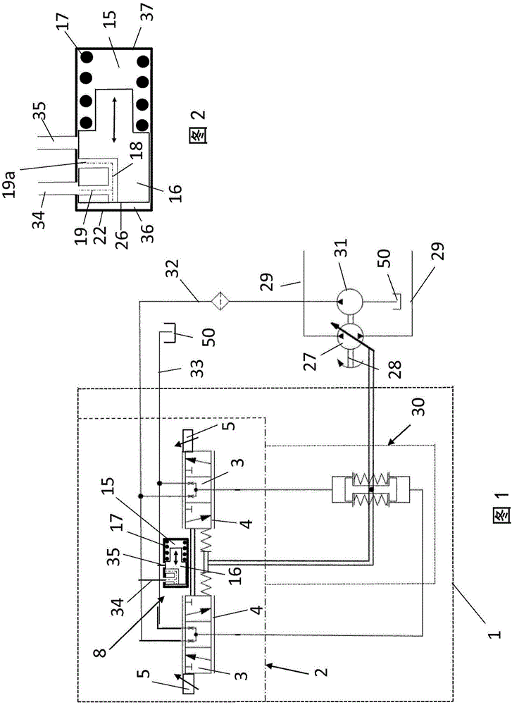
[0029] FIG. 1 shows a schematic diagram of a hydraulic machine 27 adjustable in two conveying directions with a displacement unit 1 according to the invention. The hydraulic machine, which can be a hydraulic motor or a hydraulic pump, comprises a drive or driven shaft 28 , for example for a pump, which is driven by a not shown internal combustion engine. In this case, the pump delivers fluid to and from the consumer part via line 29 . Thus, the servo displacement unit 30 is used for the adjustment of the discharge volume and delivery direction of the hydraulic fluid, which adjustment can be done, for example, by changing the displacement angle of the swash plate or the bending axis of the pump. The control of the servo displacement unit 30 is effected by the control unit 2 having two control cylinders 4 , in each of which a control slide valve 3 is movably mounted longitudinally. Thereby, the two control spool valves 3 are rigidly connected to each other, so that a displaceme...


PUM


Abstract

The invention discloses a hydrostatic displacement unit with reduced hysteresis. The invention relates to a displacement unit (1) of a hydraulic machine, for which the hysteresis is reduced. For this purpose, in the control spool (3) and/or at the control spool (3) a mass body (16) and a spring (17) are arranged, which are excited to resonance vibrations. The vibrations are self-excited and sustained by a partial flow rate of the hydraulic fluid which is modulated periodically. The high frequent vibrations are transmitted over the spring (17) onto the associated control spool (3), thereby reducing the friction and hence the hysteresis.

Description

technical field [0001] The invention relates to a hydrostatic displacement unit for stepless adjustment of the displacement of a hydraulic machine according to the general part of claim 1 . Background technique [0002] A hydraulic machine with variable displacement or critical flow includes a hydrostatic displacement unit, which sets, for example, the angular position of a swash plate or a bending axis. The displacement unit comprises two basic elements for regulating and controlling the displacement of the hydraulic machine. This is firstly the control unit, which converts the incoming mechanical, pneumatic, hydraulic or electrical control signal into a controlled volume flow for the second basic element, the servo displacement unit, which communicates with the hydromechanical The displacement element is engaged. The control unit and the servo displacement unit are connected to each other via a fluid-conducting control line which supplies, in particular discharges, the v...

Claims


Application Information

Patent Timeline
IPC IPC(8): F15B13/12F15B13/02F15C3/16F15B21/02F15B21/08F15B15/20
CPCF15B13/021F15B13/12F15B15/20F15B21/02F15B21/087F15C3/16F04B1/32F15B2211/20553F04B49/002F15B21/12F15B9/04F15B13/0402
Inventor 托马斯·莱因哈特维斯特费尔德·马丁
Owner DANFOSS POWER SOLUTIONS GMBH & CO
Why Eureka
Try Eureka