Photographing Apparatus and Method

a technology of photographing and read-out data, which is applied in the field of photographing apparatus and method, can solve the problem of taking some time to process live view images, and achieve the effects of reducing the amount of calculation during color image generation using read-out data, and reducing the amount of calculation

Inactive Publication Date: 2011-06-23
SAMSUNG ELECTRONICS CO LTD
View PDF14 Cites 33 Cited by
  • Summary
  • Abstract
  • Description
  • Claims
  • Application Information

AI Technical Summary

Benefits of technology

[0015]An image to be displayed on the display unit may be generated by directly reading out data from each pixel of the photoelectric conversion unit, or by using a representative value of each of red, green, and blue pixels of the photoelectric conversion unit. As a result, the amount of calculation during generation of a color image using the read-out data may be reduced by using the representative value.
[0016]The representative values may be calculated in advance in the photoelectric conversion unit. Also, the photographing apparatus may further include a calculation unit that calculates the representative value after data is read out from the photoelectric conversion unit. As a result, the amount of calculation during generation of a color image using the read-out data may be reduced.
[0017]When data is read out from the photoelectric conversion unit in the secon...

Problems solved by technology

Thus, when all outputs of the photographing apparatus are temporarily stored in a memory, the pro...

Method used


Image

  • Photographing Apparatus and Method
  • Photographing Apparatus and Method
  • Photographing Apparatus and Method

Examples


Embodiment Construction

[0026]The attached drawings for illustrating exemplary embodiments are referred to in order to gain a sufficient understanding of the embodiments, the merits thereof, and the objectives accomplished by the implementation of the embodiments. Hereinafter, exemplary embodiments will be described in detail with reference to the attached drawings. Like reference numerals in the drawings denote like elements.

[0027]Prior to the description of an embodiment in detail, the structure of an optical system having a lens array formed of a microlens group will be described and then the structure of a photographing apparatus having the lens array will be described.

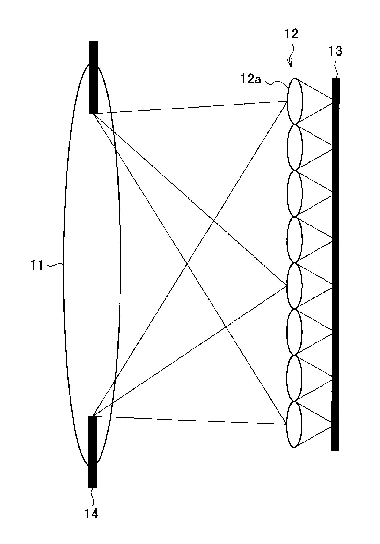
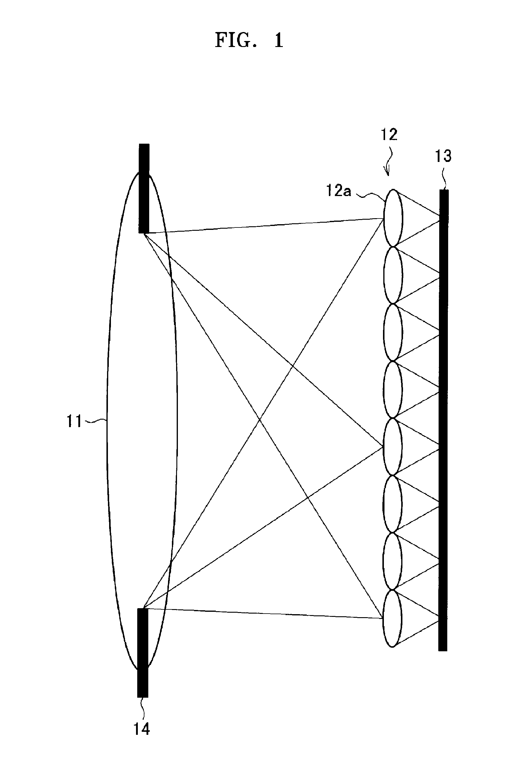
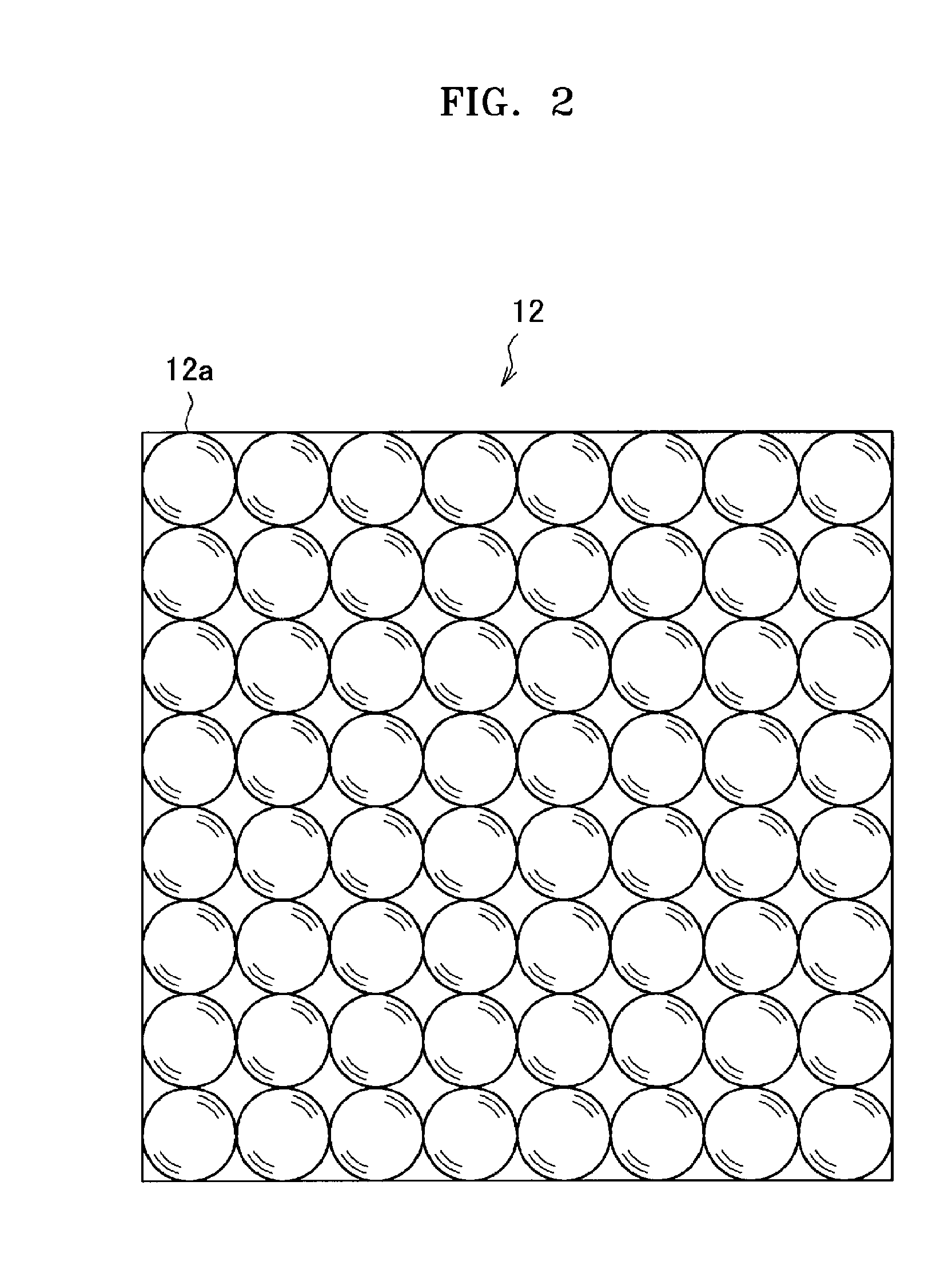
[0028]FIGS. 1 and 2 are views for explaining an optical system having a lens array formed of a microlens group. FIG. 1 is a side view showing a state in which a lens array is arranged between a lens for focusing light from an object and a photographing element. FIG. 2 is a conceptual diagram showing the arrangement of a lens array.

[0029]...


PUM


Abstract

A photographing apparatus includes a lens array and a photoelectric conversion unit. The lens array includes a plurality of lenses that are regularly arranged on a single plane. The photoelectric conversion unit includes a plurality of photoelectric conversion areas, each including a plurality of pixels. The plurality of photoelectric conversion areas are installed on a single plane. Each photoelectric conversion area corresponds to an irradiation range of light passing through a respective one of the plurality of lenses of the lens array. The photoelectric conversion unit includes a first mode and at least one second mode. In the first mode, data is continuously read out from all pixels included in the plurality of photoelectric conversion areas. In the at least one second mode, a subset of fewer than all pixels of each of the plurality of photoelectric conversion areas are selected and used to generate a color image. The selected pixels of each of the plurality of photoelectric conversion areas are at relatively the same positions with respect to each respective lens of the lens array. Data is continuously read out from the selected pixels.

Description

CROSS-REFERENCE TO RELATED PATENT APPLICATIONS[0001]This application claims the priority benefits of Japanese Patent Application No. 2009-290773, filed on Dec. 22, 2009, in the Japanese Patent Office, and Korean Patent Application No. 10-2010-0017920, filed on Feb. 26, 2010, in the Korean Intellectual Property Office, the disclosures of which are incorporated herein in their entirety by reference.BACKGROUND[0002]1. Field of the Invention[0003]Embodiments relate to a photographing apparatus and method.[0004]2. Description of the Related Art[0005]A conventional general digital still camera generates a color image signal by irradiating light focused by a focus lens onto a photographing element such as a charge-coupled device (CCD) image sensor or a complementary metal-oxide-semiconductor (CMOS) image sensor. Recently, a photographing apparatus including an optical system having a lens array formed of a microlens group arranged on a single plane between a lens and a photographing elemen...

Claims


Application Information

Patent Timeline
IPC IPC(8): H04N5/335
CPCH04N5/225H04N5/3456H04N5/343H04N23/00H04N25/42H04N25/445
Inventor MORIMOTO, YASUHIRO
Owner SAMSUNG ELECTRONICS CO LTD
Why Eureka
Try Eureka